Mission1_Blink
After you get a new board, if you don't have some previous knowledge, you might not be able to get it to work out of the box. It is so discouraging.
So this first project would like to get everyone started with basic electronic stuff and Swift language. You will try the hello world project - blink the LED. The LED will be on and off alternatively. Let's break all stuff down to see how it works.
What you need
- SwiftIO board
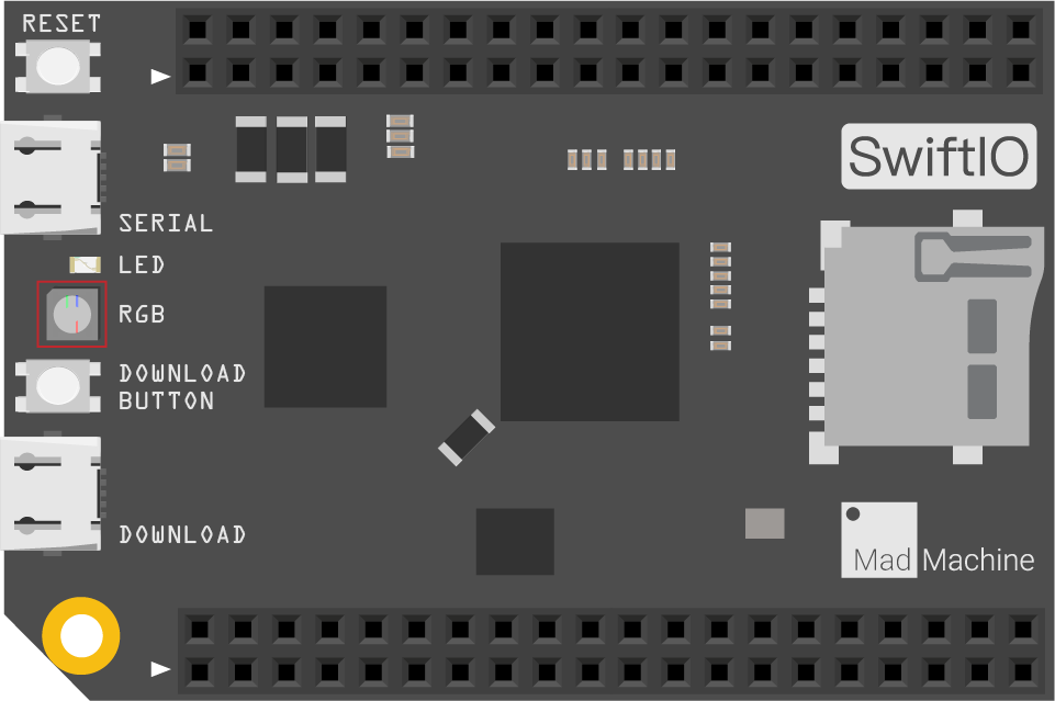
You can notice there is an onboard LED (marked with a red box above). You will only deal with it in this project, and no need for other components.
Circuit
Connect the SwiftIO board to your computer through the download port using a USB cable. There are two ports on the board. The one beside the golden ring is the download port.

Example code
Open the project Mission1_Blink in the folder MadExamples/Examples/MakerKit if you downloaded the folder.
import SwiftIO
import MadBoard

@main
public struct Mission1_Blink {
    public static func main() {
        // initialize the blue LED
        let led = DigitalOut(Id.BLUE)

        while true {
            // The code here will run all the time.

            // Set Blue LED off
            led.write(true)
            sleep(ms: 1000)	// Interval of LED blink (milliseconds)

            // Set Blue LED on
            led.write(false)
            sleep(ms: 1000)
        }
    }
}
Background
Digital signal
The digital signal usually has two states, represented as either 1 or 0. For the SwiftIO board, 1 represents 3.3V, and 0 represents 0V. Besides, you can also describe the states using high or low, true or false. In this project, you will set the digital output to turn on or off an LED.

LED
The LED, or light-emitting diode, is one kind of diode. It has a positive leg (anode) and a negative leg (cathode). The long leg is positive, and the short leg is negative. The current can only flow in one direction, from positive to negative. Therefore, only when you connect it in the right direction, the current can flow. Or, the LED won't be lighted.

There are two ways to connect an LED to your circuit:
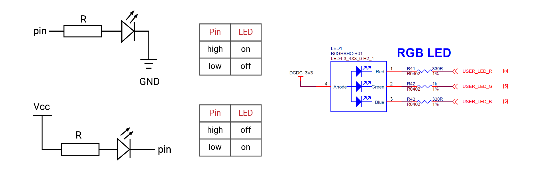
-
Connect the LED to a digital pin and ground (GND), as shown in the upper left corner. The current always flows from high to low voltage.
- If the pin outputs a high voltage, the current flows from that pin to GND, hence the LED will be on.
- On the contrary, if it outputs a low voltage, there's no current and the LED turns off.
-
Connect the LED to the power (Vcc) and a digital pin, as shown in the lower left corner. This is how the onboard LED works. The diagram on the right shows its circuit connection.
- If the pin outputs a high voltage, there is no voltage difference between the two ends of the LED, so the LED is off.
- When the pin outputs a low voltage, the current can flow from the power to that pin, and the LED will be on.
You can find an LED beside the download button on your board. It is a different type for easier soldering. This RGB LED has three colors: red, green and blue. As you download the code, it serves as a status indicator. Besides, you can also control its color and state by setting the output voltage.
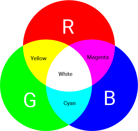
- You can light any one of them, which means the red, green, or blue LED will be turned on.
- You can also turn on two of them. For example, if you choose red and blue, you can notice the light appears magenta.
- If all three LEDs are on, the light becomes white.
Code analysis
Let's look into the code in detail:
import SwiftIO
import MadBoard
SwiftIO consists of all the functionalities to control your board. All programs must first reference it so you can use everything in it, like classes and functions.
MadBoard defines the corresponding pin ids of all boards, including the SwiftIO board.
let led = DigitalOut(Id.BLUE)
Before you set a specific pin, you need to initialize it.
- First, declare a constant: use the keyword
letfollowed by a constant nameled. - Then make it an instance of
DigitalOutclass to initialize that pin. - To initialize the pin, you need to indicate its
id. All ids are in an enumeration, and the built-in RGB LEDs use the id RED, GREEN, or BLUE. Thus the id of blue LED here is written asId.BLUEusing dot syntax.
while true {

}
Within the dead loop while true, the code will run over and over again unless you power off the board.
led.write(true)
The method write(_:) sets the pin to output high or low voltage. Its parameter is a boolean type: true corresponds to a high level, and false corresponds to a low level. As mentioned above, The onboard LED is connected to 3.3V internally. If you set it to high voltage, there will be no current. If you apply low voltage, it will be on.
sleep(ms: 1000)
The function sleep(ms:) will stop the microcontroller's work for a specified period. The period is specified in milliseconds. It is a global function in the library, so you can directly use it in your code.
So the code above makes LED alternate between off and on every second.
Reference
DigitalOut - set whether a digital pin outputs a high or low voltage.
sleep(ms:) - suspend the microcontroller's work for a specified time, measured in milliseconds.
MadBoard - find the corresponding pin ids of your board.