Mission5_Buzzer
In this project, you will get a buzzer buzzing. Its sound will change as you turn the potentiometer.
What you need
The parts you will need are all included in the Maker kit.
- SwiftIO board
- Shield
- Buzzer module
- Potentiometer module
- 4-pin cables
Circuit
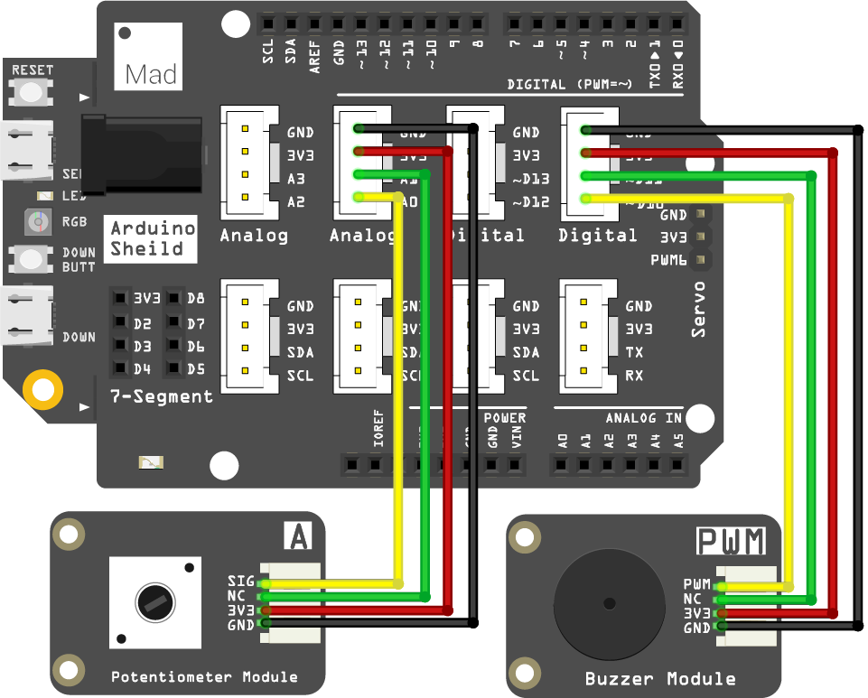
- Plug the shield on top of your SwiftIO board.
- Connect the potentiometer module to pin A0 using a 4-pin cable.
- Connect the buzzer module to pin PWM2B (D10) using a 4-pin cable.
Example code
Open the project Mission5_buzzer in the folder MadExamples/Examples/MakerKit if you downloaded the folder.
import SwiftIO
import MadBoard

@main
public struct Mission5_Buzzer {
    public static func main() {
        let a0 = AnalogIn(Id.A0)

        // PWM, also known as Pulse Width Modulation is a type of digital signal.
        // The PWM signal can be used to configure a servo, or to control the dimming of a LED light.
        // Initialize a PWM output pin.
        let buzzer = PWMOut(Id.PWM2B)

        while true {
            // Read the input voltage.
            let value = a0.readPercentage()

            //let value = a0.readPercentage()
            let frequency = Int(400 + 2000 * value) // calculate the float value into Int type to serve as frequency.
            buzzer.set(frequency: frequency, dutycycle: 0.5) // Set PWM parameters.

            sleep(ms: 20) // Set the duration of the notes.
        }
    }
}
Background
Pulse Width Modulation (PWM)
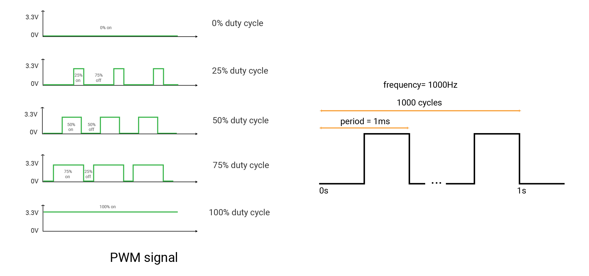
Pulse Width Modulation (PWM) can simulate analog results digitally. The signal is still a square wave that switches between on and off. The duration of the "on-time" is called the pulse width. So this technique will change the duration of the high level relative to the low level and switch extremely quickly between them. In this way, it will simulate the voltage between fully open (3.3 volts) and off (0 volts).
When you repeat this switching pattern with LEDs fast enough, your eyes cannot notice the quick changes between on and off, thus it seems the LED would show different brightness to your eyes. If the change is not quick enough, you may detect it and the LED seems to flicker.
Now come more concepts. A fixed time period consists of on and off time. The period is the inverse of the PWM frequency. For example, when the PWM frequency is 1000 Hz, one period is 1 millisecond.
The duty cycle is the percentage of on-time of output signal during one period. Its range is 0-1.
- 1 means the voltage is always high.
- 0 means the voltage is always low.
- The signal with a 0.5 duty cycle is on for 50% of the time and off for 50% of the time.
Buzzer
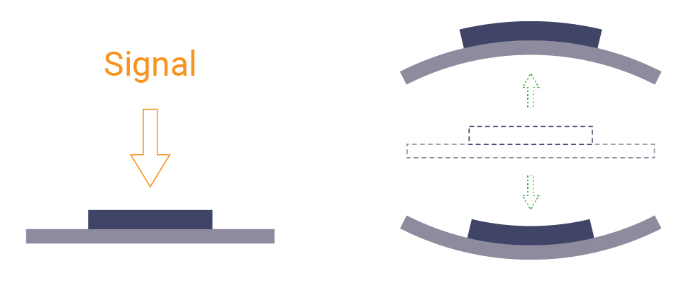
The buzzer can buzz when you apply voltages. That's because the diaphragm inside it can move back and forth as the signal switches between on and off. The vibration causes the surrounding air to vibrate and finally causes the sound you hear.
There are two kinds of buzzers.
- An active buzzer has an internal circuit to create alternating voltage. So you just need to connect it to power. But it can only generate a constant sound since the voltage cannot change.
- A passive buzzer needs PWM signals. When the signal switches between on and off, the internal diaphragm moves with it. The frequency of the signal will influence the pitch. A higher frequency will produce a higher pitch. That's how this projects works.
Code analysis
import SwiftIO
import MadBoard
First, import the two libraries: SwiftIO and MadBoard to use everything in it. SwiftIO is used to control the input and output of the board. MadBoard defines the pin name of the board.
let a0 = AnalogIn(Id.A0)
let buzzer = PWMOut(Id.PWM2B)
Initialize the analog pin (A0) for the potentiometer and the PWM pin (PWM2B) for the buzzer.
let value = a0.readPercentage()
let frequency = Int(400 + 2000 * value)
Read the analog value in percentage and store it in the constant value. The frequency is calculated based on this value. In this case, it's from 400 Hz to 2400 Hz. The bigger the value, the higher the frequency.
buzzer.set(frequency: frequency, dutycycle: 0.5)
Set the PWM signal. The method set(frequency:dutycycle:) has two parameters: frequency and duty cycle. Its frequency is related to the analog value above. The duty cycle doesn't matter in this project, and you can set it to 0.5 or any value.
Reference
PWMOut - set the PWM signal.
AnalogIn - read the voltage from an analog pin.
MadBoard - find the corresponding pin ids of your board.