Mission3_Push_Button
In the two previous projects, the LEDs turn on and off automatically. Now, you will control the LED manually using a button.
What you need
The parts you will need are all included in the Maker kit.
- SwiftIO board
- Shield
- Button module
- 4-pin cable
Circuit
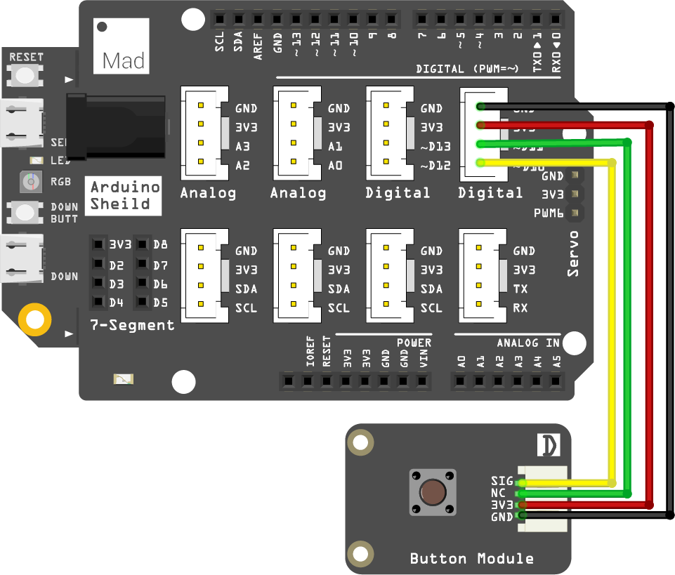
The shield is a modular circuit board for easier circuit connection. The pins on the two sides match those on the SwiftIO board. Besides, it has many grove connectors They need a 4-pin cable instead of four jumper wires, so you would build the circuits more easily.
- Plug the shield on top of your SwiftIO board. Make sure you connect them in the right direction.
- Connect the button module to pin D10 using a 4-pin cable. Each cable has four colors of wires: the black is usually for ground, and the red one is for power.
Ok, the circuit is complete. It is so convenient, isn't it?
Example code
Open the project Mission3_Push_Button in the folder MadExamples/Examples/MakerKit if you downloaded the folder.
import SwiftIO
import MadBoard

@main
public struct Mission3_Push_Button {

    public static func main() {
        let led = DigitalOut(Id.RED) // Initialize the red onboard led.
        let button = DigitalIn(Id.D10) // Initialize an input pin D10 on board.

        while true {
            // Read the button value. If it is pressed, turn on the led.
            if button.read() {
                led.write(false)
            } else {
                led.write(true)
            }

            sleep(ms: 10)
        }
    }
}
Background
Button
A button, or pushbutton, is always used to control other devices. You can see it in a light switch, remote control, etc. This button is momentary, so its state will only change as you press it. Once you release it, it will go back to its original state.
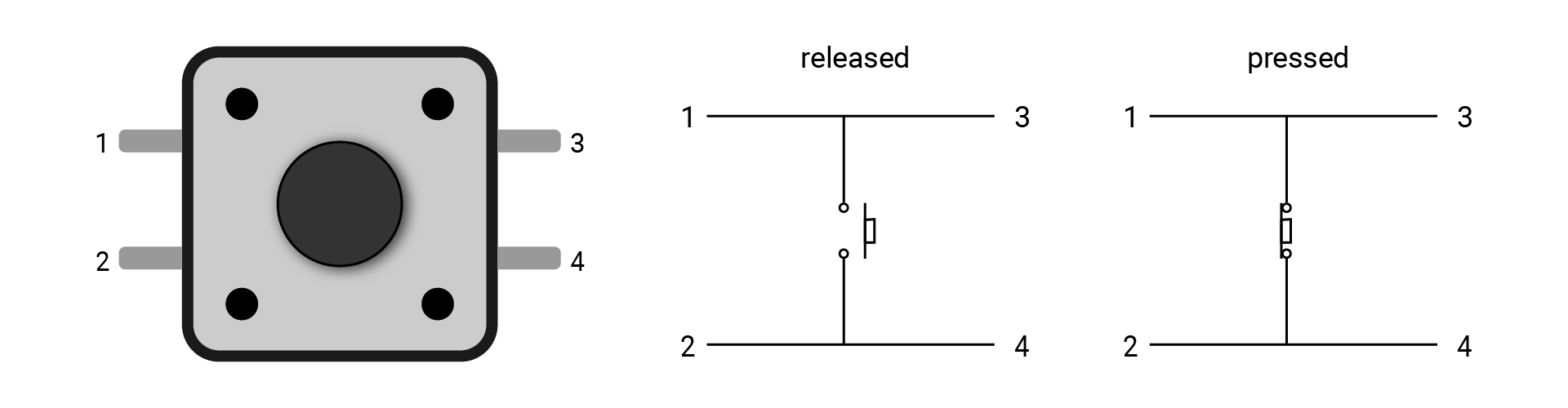
This kind of button usually has four legs. Every two legs are shorted, like 1 and 3, 2 and 4. If you connect both 1 and 3 to your circuit, the current can flow through it all the time, thus the button plays no role. It's a good idea to connect the two legs on a diagonal line in the circuit, like 1 and 4, 2 and 3.
While the button module in your kit uses the grove connector, you can directly build the circuit without worrying about the wrong connection.
Also, there is a known issue with the button: the bounce. The button module uses the hardware debounce method, so you will not meet with this issue.
Code analysis
import SwiftIO
import MadBoard
First, import the two libraries: SwiftIO and MadBoard to use everything in it. SwiftIO is used to control the input and output of the board. MadBoard defines the pin name of the board.
let led = DigitalOut(Id.RED)
let button = DigitalIn(Id.D10)
Initialize the red onboard LED and the digital pin (D10) that the button connects. Only their ids are required during initialization.
In the loop, you will use the if-else statement to check the button states. It has the following form:
if condition {
    statement1
} else {
    statement2
}
The condition has two results, either true or false. If it is true, statement1 will be executed; if it's false, statement2 will be executed.
Then let's look back to the code.
if button.read() {
    led.write(false)
} else {
    led.write(true)
}
The method read() allows you to get the input value, either true or false. It's related to the state of the button.
- If the button is pressed, the returned value will be
true. Then the pin output a low voltage to turn on the onboard LED. - Once you release the button, the input value becomes
false. Consequently, the LED will turn off.
Reference
DigitalOut - set whether a digital pin outputs a high or low voltage.
DigitalIn - read the input value from a digital pin.
MadBoard - find the corresponding pin ids of your board.