Know your hardware
In this tutorial, you will get to know the hardware that will be your companion throughout this learning journey.
The SwiftIO Playground kit consists of two parts:
- SwiftIO Micro - main board
- SwiftIO Playground - expansion board
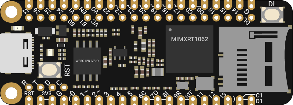
SwiftIO Micro
By connecting it to various hardware components and downloading code onto it, you can interact with the real world, utilizing sensors to detect the environment or generating outputs such as lights and speakers.
While compact in size, the SwiftIO Micro is incredibly powerful. It is capable of handling all kinds of your projects and can be easily integrated into any of your creative endeavors.
What's more, the SwiftIO Micro is compatible with the Adafruit Feather system, allowing you to combine it with the hardware available in their system.
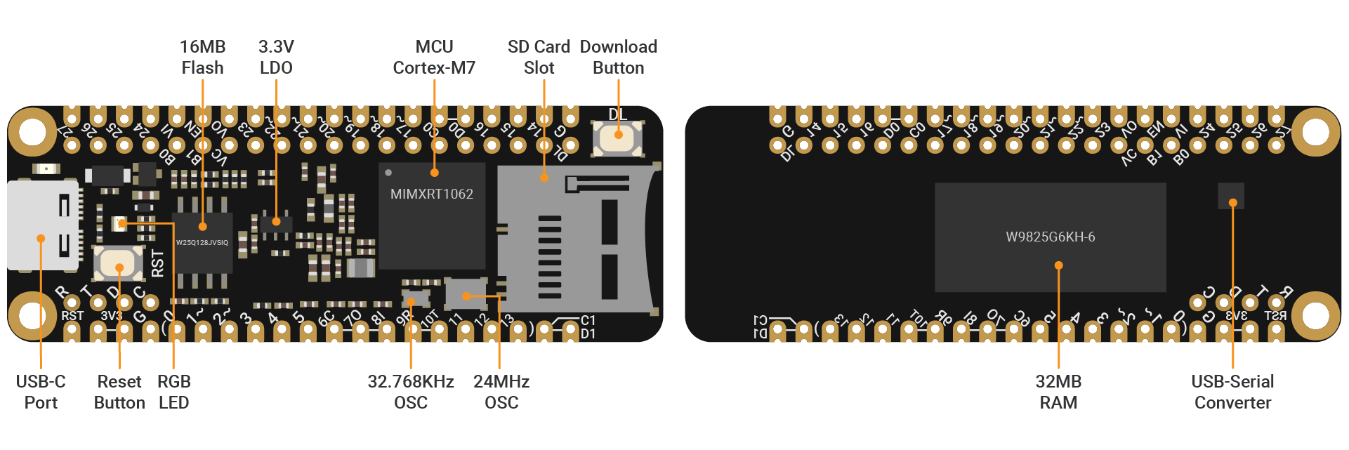
Now, let's delve into the details of the board:
| Part | Detail |
|---|---|
| MCU | i.MX RT1062 Crossover Processor with Arm® Cortex®-M7 core @600MHz |
| Storage | 16MB flash, 32MB external RAM |
| Power | 3.3V |
| LED | onboard RGB LEDs |
| USB port | USB-C, used to download the code, print values, as well as power the board |
| GPIO | 44 (D0-D43), used for digital input or output |
| ADC | 14 (A0-A13) 12-bit resolution analog to digital converter, used for analog input |
| PWM | 14, used for PWM output |
| I2C | 2 (I2C0, I2C1), SCL and SDA pins used for I2C communication |
| SPI | 2 (SPI0, SPI1), SCK, SDO, SDI pins used for SPI communication |
| UART | 3 (UART0-UART2), RX and TX pins used for UART communication |
| I2S | 1 (I2S0), SYNC, BCLK and RX/TX pins used for I2S audio input |
| CAN | 1, CTX and CRX pins used for CAN communication |
You can connect other hardware to the board through the pins on two sides. This is the pinout diagram of SwiftIO Micro. It shows the usage of all pins.
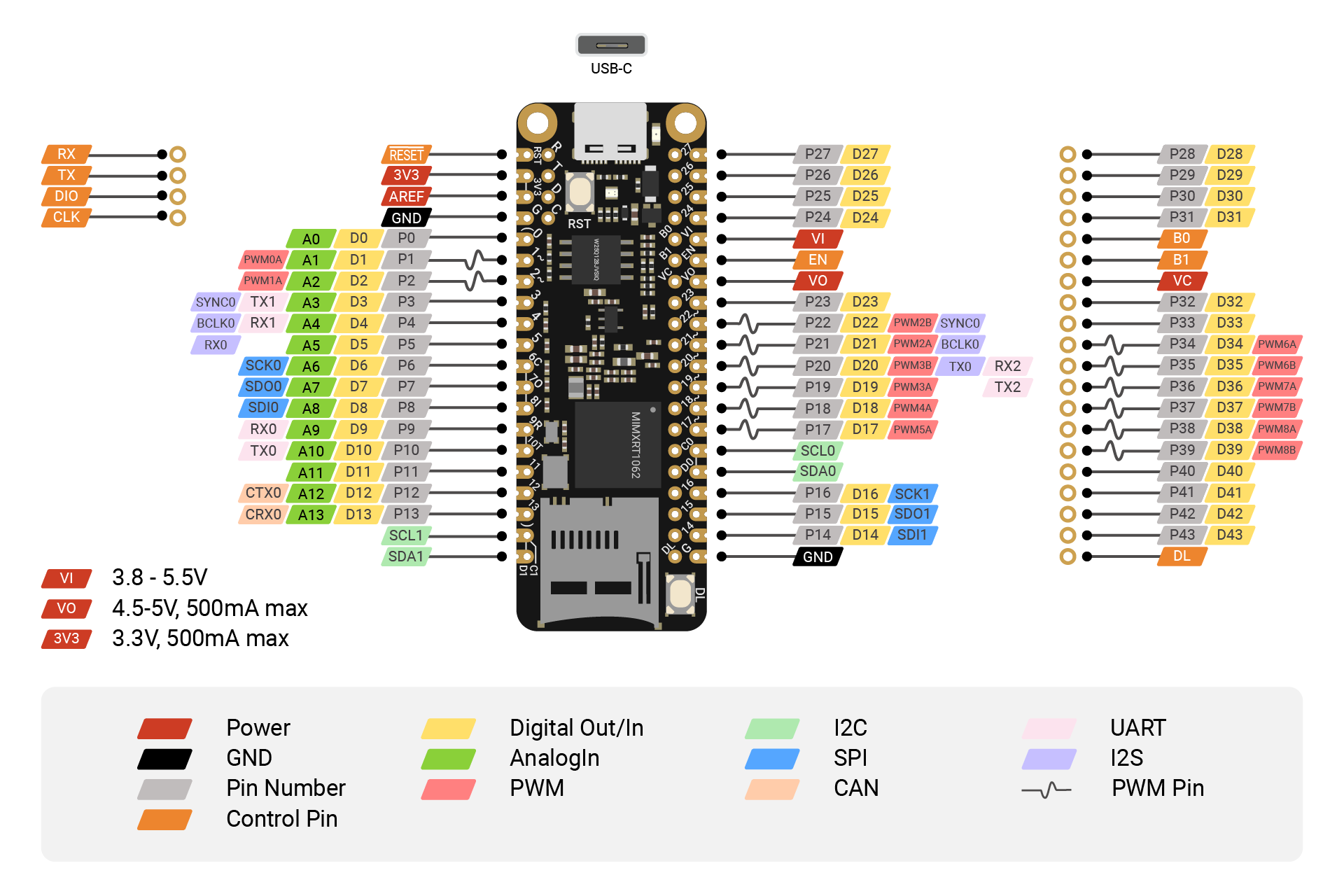
As mentioned before, most pins on the board are multiplexed, therefore you need to decide the pin's usage in your code.
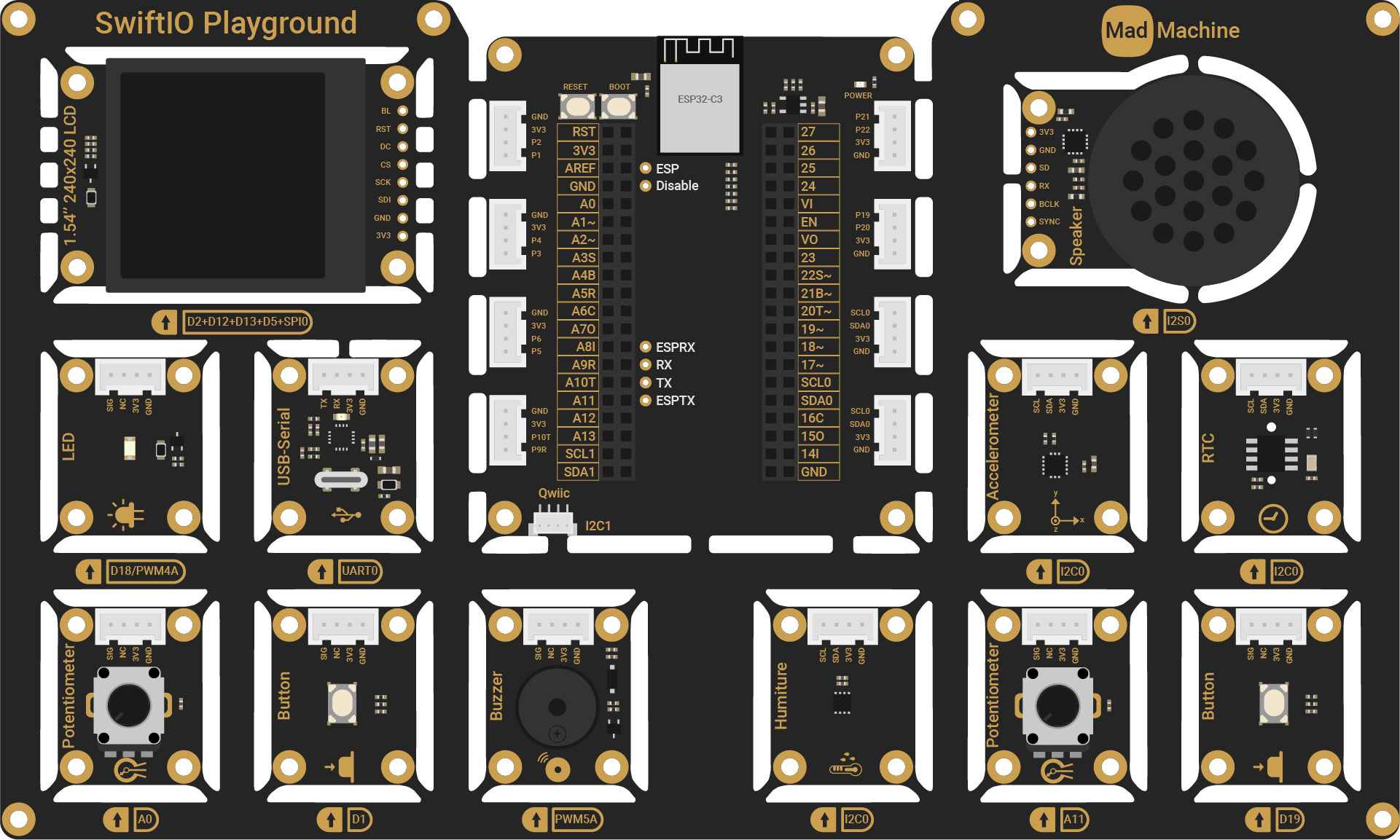
SwiftIO Playground
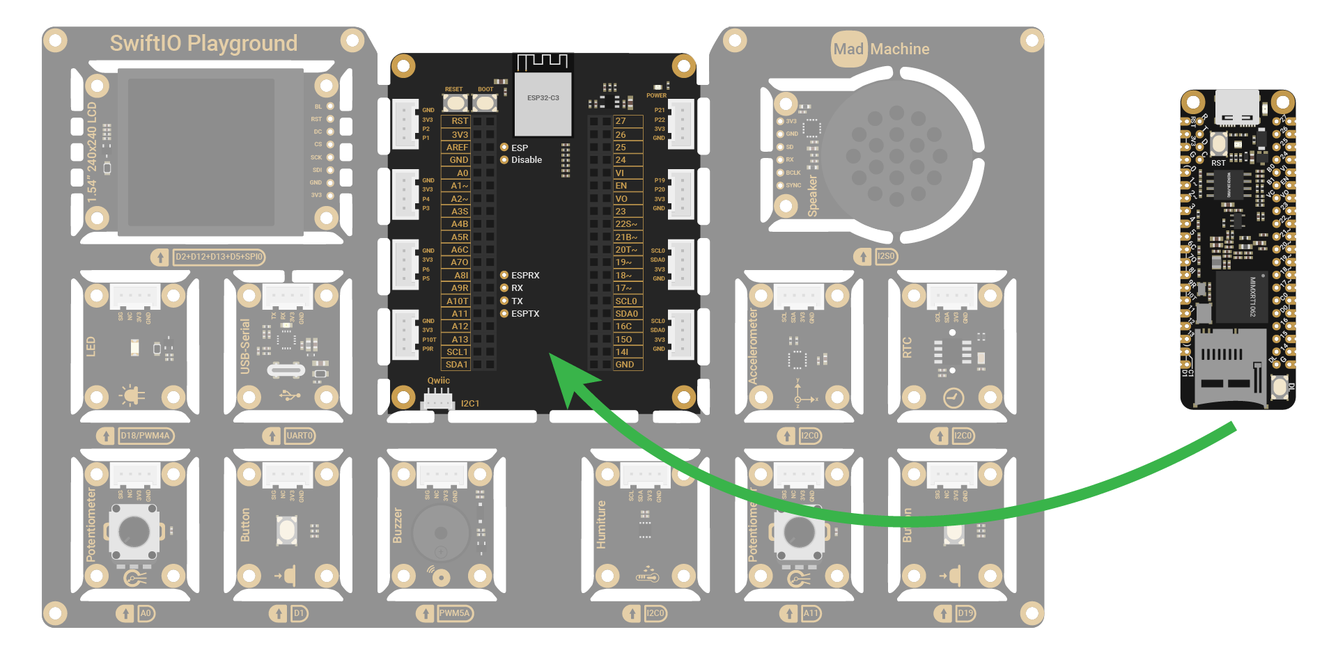
Only with the SwiftIO Micro, you may still don't know how to start. The expansion board - SwiftIO Playground is specially designed for all newbies to get started. No wire is needed! All modules are directly connected to the shield in the middle.
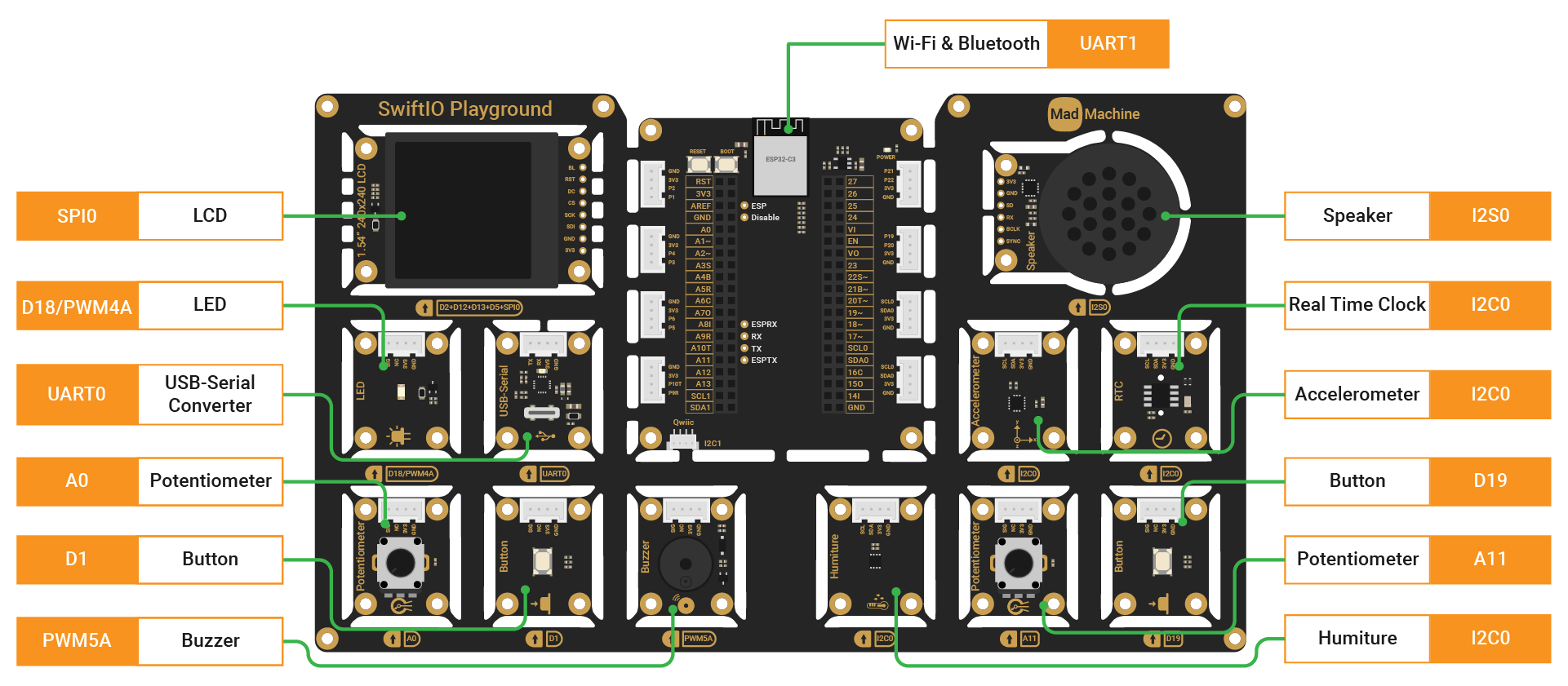
The shield in the middle is for easier connection, and it's the SwiftIO Micro that communicates with all the modules. After you plug the SwiftIO Micro into the shield, the circuit is built. Then you could program the SwiftIO Micro to control the modules.
Let's look into these modules in detail:
| Module | Quantity | Description |
|---|---|---|
| LED | 1 | Can be toggled on and off, or set to any brightness. |
| Button | 2 | Control the current flow in circuits as you press or release it. |
| Potentiometer | 2 | Vary resistance connected in the circuit. |
| Buzzer | 1 | Produce sounds of different pitches. |
| Humiture | 1 | Measure temperature and humidity. |
| Real Time Clock | 1 | Read the current time and date. |
| Accelerometer | 1 | Detect movement by measuring the acceleration. |
| Speaker | 1 | Generate sounds or play the audio files back. |
| USB-Serial Converter | 1 | Connect to the USB port of another device to transmit serial data. |
| LCD | 1 | Display graphics or images. |
| ESP32-C3 | 1 | Serve as a Wi-Fi module. |
You may wonder why some modules have a connector, while others don't.
These connectors are provided in the event that you wish to disassemble the board. Please note that disassembly is a one-way process, though, and you will not be able to reconnect the parts through the included board. Once apart, use 4-pin cables to connect the module to the shield. Some modules (like LCD) don't have a connector since they require more than 4 wires and don't support 4-pin connectors.
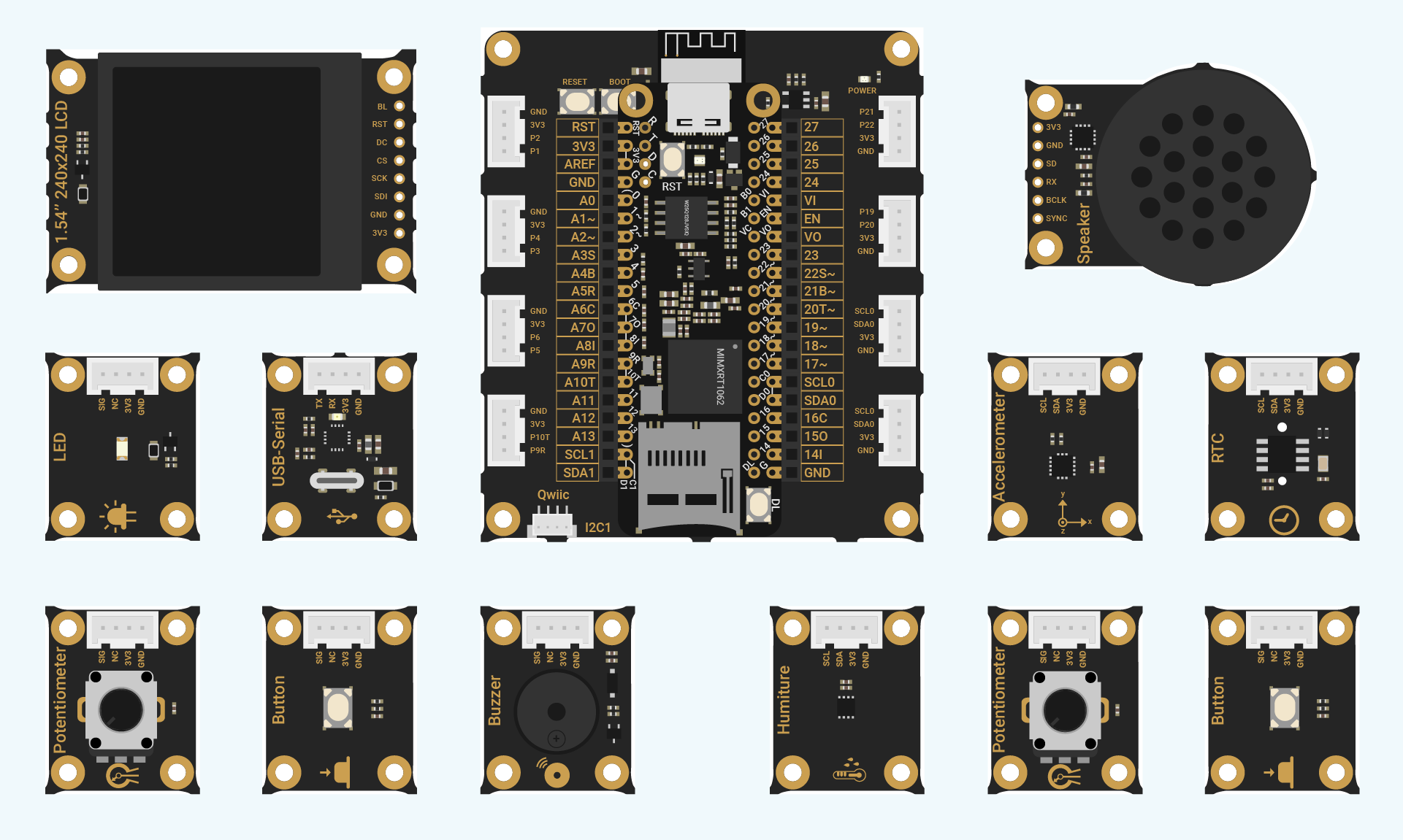
Make sure not to connect these modules to the shield through the connectors since they are already connected through the board!
How can you disassemble the board?
The modules can be separated by cutting as shown below.

Once again, you cannot put the board back together and once you've broken it apart, you will need to connect any circuits manually using cables.