UART
In this tutorial, let's delve into UART communication.
Learning goals
- Know about parallel and serial communication.
- Distinguish between synchronous and asynchronous communication.
- Learn about the UART protocol.
- Understand the usage of USB-Serial converter.
🔸Circuit - USB-Serial Converter
The USB-Serial Converter connects to UART0.
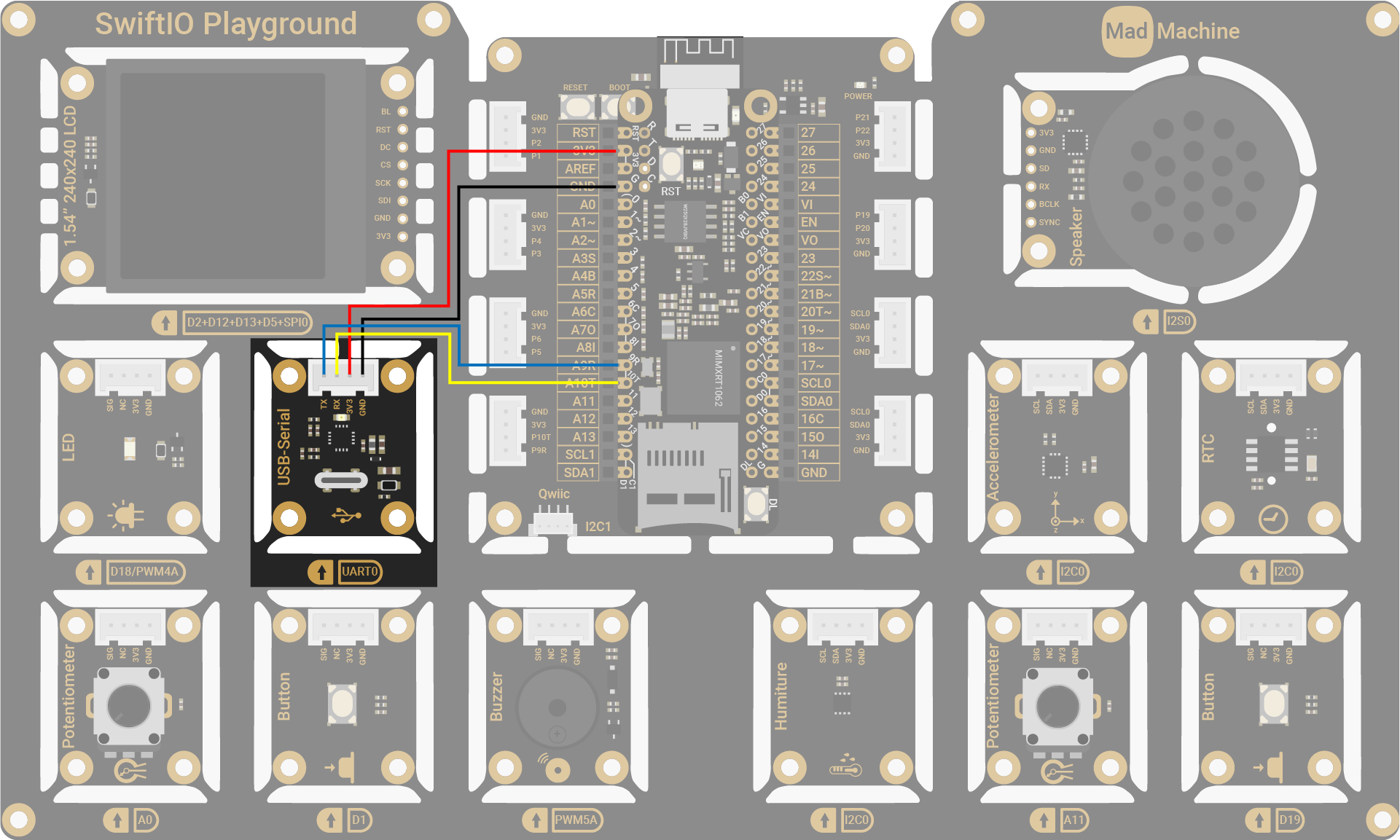
| USB-Serial Converter Pin | SwiftIO Micro Pin |
|---|---|
| TX | UART0 (RX) |
| RX | UART0 (TX) |
| 3V3 | 3V3 |
| GND | GND |
The circuits above are simplified versions for your reference. Download the schematics here.
🔸Projects
1. Serial echo
In this project, the board acts as an echo device, sending back the messages it receives from the computer. By connecting to a serial monitor, you can easily view the messages being echoed by the board.
Project overview
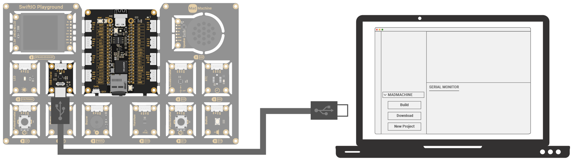
- Connect the USB-Serial Converter to the USB port of your computer and choose the corresponding port on the serial monitor.
- Type a message in the serial monitor's input field and send the message to the board.
- After the board receives the message on the UART port, it will echo it back to the computer. You should see the echoed message in the serial monitor.
Example code
You can download the project source code here.
// Send message from computer to USB-Serial converter using serial monitor.
// Then send the message back using UART.
import SwiftIO
import MadBoard


let uart = UART(Id.UART0)

var message = [UInt8](repeating: 0, count: 100)

while true {
    // Check if there is available data in the UART buffer.
    let count = uart.checkBufferReceived()

    if count > 0 {
        for i in message.indices {
            message[i] = 0
        }
        // Read data from the buffer.
        uart.read(into: &message, count: count)
        // Send the message back.
        uart.write(Array(message[0..<count]))
    }

    sleep(ms: 10)
}
Code analysis
let uart = UART(Id.UART0)
The default UART settings are as follows:
- Baud Rate: 115200
- Stop Bit: 1
- Data Bits: 8
- Parity: None
Make sure that the serial monitor on your computer is configured to match these settings.
let count = uart.checkBufferReceived()
As mentioned before, UART has a receive buffer for incoming data. This statement checks the receive buffer and determines the number of bytes that are currently available for reading.
uart.read(into: &message, count: count)
Read the incoming bytes from UART's receive buffer and store them in the array. The receive buffer is then cleared for new incoming data.
uart.write(Array(message[0..<count]))
Send received bytes back to the computer, allowing them to be displayed on the serial monitor.
2. Serial LED switch
Turn on/off the LED by sending commands from your computer.
Project overview
- Connect the USB-Serial Converter to the USB port of your computer and choose the corresponding port on the serial monitor.
- Send 1 from the computer to turn on the LED.
- Send 0 from the computer to turn off the LED.
Example code
You can download the project source code here.
// Connect the USB-Serial converter module to your computer
// and choose the port in serial monitor.
// Send message (1/0) from computer to turn on/off the LED.

import SwiftIO
import MadBoard


let uart = UART(Id.UART0)
let led = DigitalOut(Id.D18)

while true {
    // Check if there is any message from computer.
    let count = uart.checkBufferReceived()

    if count > 0 {
        // Read data from UART buffer.
        var buffer = [UInt8](repeating: 0, count: count)
        uart.read(into: &buffer)

        // Decode the data since the text from computer is sent in UTF8 format.
        let command = String(decoding: buffer, as: UTF8.self)
        // Connect the port on your micro board in serial monitor to see printed message
        print(command)

        // Set digital output according to the command from computer.
        switch command  {
        case "0": led.low()
        case "1": led.high()
        default: break
        }
    }

    sleep(ms: 10)
}
Code analysis
let command = String(decoding: buffer, as: UTF8.self)
UART transmits data as a sequence of 0s and 1s. It doesn't have built-in support for specific encoding formats like UTF-8.
When you receive data through UART, it arrives as a stream of binary bits. To make sense of this data, you need to process and interpret it according to the desired encoding format, such as UTF-8.
3. Remote LED switch
Implement a remote LED switch with two boards connected via UART
Project overview
- Connect two boards to your computer using USB cables. Then two boards are connected through the UART0 port:
- RX0 of board 1 (left board in the image) connected to TX0 of board 2 (right board in the image),
- TX0 of board 1 connected to RX0 of board 2.
- If the button (D1) is pressed/released, board 1 will send the corresponding command via the UART bus to board 2.
- Board 2 will receive the command and turn on/off the LED (D18) connected to it based on the received command.
Example code
You can download the project source code here.
- Board 1 connected to button
- Board 2 connected to LED
// This code is downloaded to board connected to a button.
// Detect if the button is pressed/released and send message to another board via UART bus.
// Connect UART0 (RX/TX) of this board to the UART0 (TX/RX) of the other board.

import SwiftIO
import MadBoard


let uart = UART(Id.UART0)

#if SWIFTIOMICRO
let button = DigitalIn(Id.DL)
#else
let button = DigitalIn(Id.D0)
#endif

var buttonPressed = false

while true {
    let pressingButton = button.read()

    // If button is pressed, send message to turn on LED connected to another board.
    if pressingButton && !buttonPressed {
        uart.write("on")
        buttonPressed = true
    }

    // If button is released, send message to turn off LED connected to another board.
    if buttonPressed && !pressingButton {
        uart.write("off")
        buttonPressed = false
    }

    sleep(ms: 5)
}
// This code is downloaded to board connected to an LED.
// Wait UART data from other board to turn on/off LED.
// Connect UART0 (RX/TX) of this board to the UART0 (TX/RX) of the other board.

import SwiftIO
import MadBoard


let uart = UART(Id.UART0)
let led = DigitalOut(Id.BLUE)

var buffer: [UInt8] = []

while true {
    // Receive all data from another board via UART bus.
    while uart.checkBufferReceived() > 0 {
        var byte: UInt8 = 0
        uart.read(into: &byte)
        buffer.append(byte)
        sleep(ms: 1)
    }

    // Match the message and change the LED state.
    if buffer.count > 0 {
        // The message from another board is sent in cString
        // which means the last data is 0, so you need to convert
        // the data in buffer to string using the given encoding.
        let command = String(cString: buffer)

        buffer.removeAll()

        switch command {
        case "on":
            led.high()
        case "off":
            led.low()
        default: break
        }
    }

    sleep(ms: 10)
}
Make sure that only one board is connected to the computer at a time for code upload.
🔸API
UART
This class allows you to write and read data via the UART bus.
init(_ idName: IdName, baudRate: Int = 115200, parity: Parity = .none, stopBits: StopBits = .oneBit, dataBits: DataBits = .eightBits, readBufferLength: Int = 1024)
Initialize a UART interface.
Parameter:
idName: id of the UART interface that the device connects to.baudRate: the baud rate for UART communication, 115200 by default.parity: the parity bit to ensure the data transmission. By default, no parity bit is used.stopBits: the number of stop bit, 1 bit by default.dataBits: the number of data bits, 8 bits by default.readBufferLength: the length of receive buffer, 64 bytes by default. Make sure it's large enough to store data.
func read(into buffer: inout UInt8, timeout: Int? = nil) -> Result<Int, Errno>
Read a byte from the external device and store it into the provided buffer.
Parameter:
buffer: a UInt8 to store the received byte.timeout: the max time limit (in milliseconds) for data reception. By default, wait until all data is received before returning. It it's not nil,- -1: wait until all required data are received.
- 0: return immediately, regardless of whether data is available to read or not.
- A positive integer: wait for a specified period (in milliseconds), then stop reading data when time is up, even if not all needed data are got.
Return value:
- The number of data that is still needed for the success case, or an error for the failure case.
func read(into buffer: inout [UInt8], count: Int? = nil, timeout: Int? = nil) -> Result<Int, Errno>
Read a specified amount of bytes from the external device and store it into the provided buffer.
Parameter:
buffer: a UInt8 array to store the received byte.count: the number of bytes to read. Make sure it doesn't exceed the length of the buffer. If it's nil, it equals the length of the buffer.timeout: the max time limit (in milliseconds) for data reception. By default, wait until all data is received before returning. It it's not nil,- -1: wait until all required data are received.
- 0: return immediately, regardless of whether data is available to read or not.
- A positive integer: wait for a specified period (in milliseconds), then stop reading data when time is up, even if not all needed data are got.
Return value:
- The number of data that is still needed for the success case, or an error for the failure case.
func write(_ data: [UInt8], count: Int? = nil) -> Result<(), Errno>
Writes bytes to the external device through the serial connection.
Parameter:
data: an array of UInt8 to be sent to the device.count: the number of bytes indatato be sent. Make sure it doesn't exceed the length of thedata. If it's nil, all data will be sent.
func checkBufferReceived() -> Int
Returns the number of received data from the serial buffer.
Return value:
- The number of bytes received in the buffer.
🔸Background
Dive deeper into communication
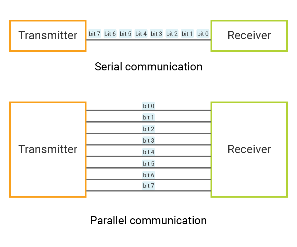
Parallel and Serial communication
To recap quickly, communication protocols are a set of rules that dictate how data is exchanged between devices. Typically, data is represented as a sequence of 0s and 1s, which are transmitted as digital signals between devices using different types of communication.
Depending on how these bits are sent, communication can be typically categorized as either parallel or serial.
| Parallel communication | Serial communication | |
|---|---|---|
| Transmission | multiple bits sent at the same time over multiple data lines | bits are transmitted one after another over a single communication channel |
| Example | communication between a CPU and memory | I2C, SPI, UART |
| Characteristic | allows high-speed data transfer | requires fewer wires |
Synchronous and Asynchronous communication
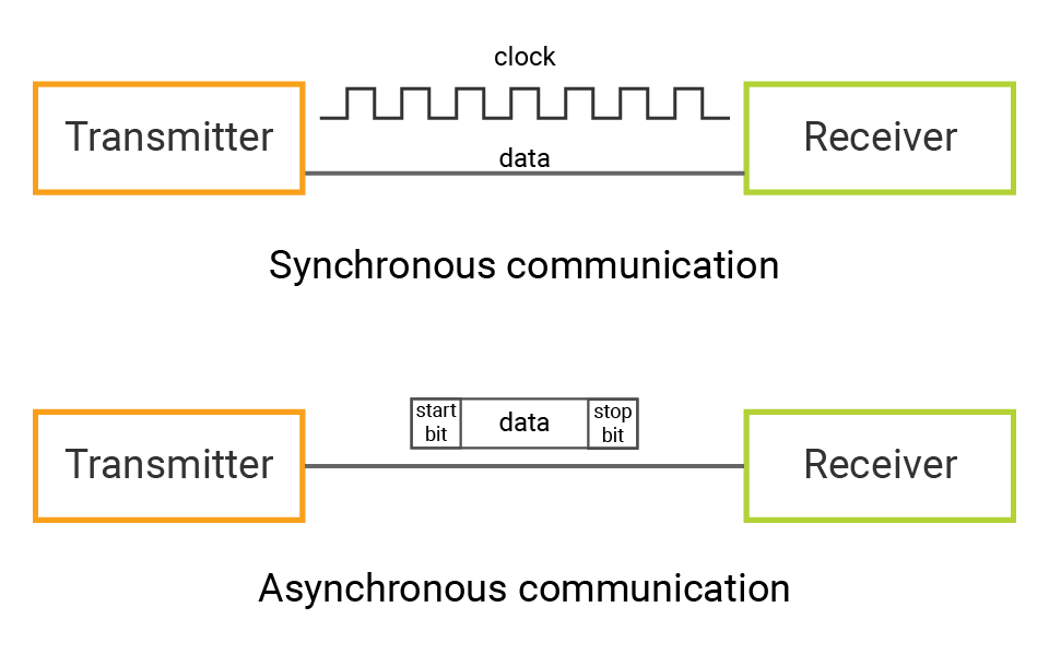
If you are a software programmer, you may be familiar with the terms Synchronous and Asynchronous. However, in this context, we are referring to Synchronous and Asynchronous communication protocols. The primary difference between synchronous and asynchronous communication protocols lies in the use of a clock signal.
I2C and SPI are both examples of synchronous communication protocols. In synchronous communication,
- The master device generates a clock signal to synchronize the data transmission between the master and slave devices.
- The clock signal specifies the duration of each bit and the rate at which bits are transmitted.
- The data is typically read or sent at the rising or falling edge of the clock signal.
In asynchronous communication protocols like UART,
- There is no clock signal to synchronize the transmission of data.
- Instead, each data stream is accompanied by start and stop bits that indicate the beginning and end of the data transmission.
- The transmitter and receiver independently calculate the timing of each bit based on a predefined baud rate.
What is UART?
UART stands for Universal Asynchronous Receiver-Transmitter, which means it is a type of serial communication protocol that uses an asynchronous method for transmitting and receiving data between two devices.
❖ UART bus
The UART bus consists of a Transmitter (TX) and Receiver (RX), which are used for data transmission between two devices. The TX line of one device should be connected to the RX line of the other device, and vice versa. This allows the two devices to transmit and receive data to and from each other.

❖ Data transmission
UART communication is asynchronous, which means that the transmitter and receiver don't share a clock signal to synchronize their actions.
Thus, the start and stop bits are necessary, which allows the receiving device to synchronize its internal clock with the data stream and accurately interpret the data being transmitted.
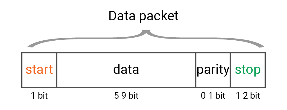
In UART communication, data is transmitted in packets. Each packet consists of several components:
- The start bit is the first component to signal the beginning of the transmission.
- The data frame follows the start bit and contains the actual data (5 - 9 bits) being transmitted. It is typically composed of 8 bits.
- If parity is used, an additional parity bit is added after the data frame to detect errors in the transmission. It counts the number of 1s in the data frame and can be even, odd, or none.
- Finally, stop bit(s) is added at the end of the packet to signal the end of the transmission. The stop bit is always a logical high level. The number of stop bits can be one or two.
The most common configuration is 8 data bits, 1 stop bit, and no parity bit.
❖ Baud rate
In order to accurately interpret the data being transmitted, both the transmitter and receiver must use the same baud rate. Baud rate is the number of symbols transmitted over a communication channel per second, typically expressed in bits per second (bps) in this case.
If the baud rates do not match, the receiver may interpret the data incorrectly, resulting in errors in the received data. For example, if the transmitter uses 9600 baud rate while the receiver uses 19200 baud rate, the receiver may sample the data at a different rate than it is being transmitted, causing it to misinterpret the data.
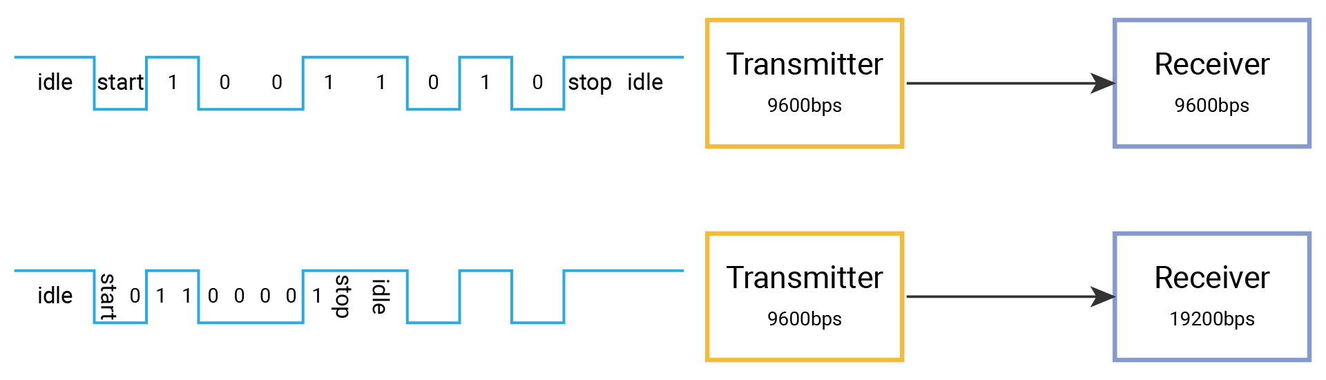
Some common baud rates used in UART communication are 9600, 19200, 38400, 57600, 115200...
Peripheral - UART
A UART peripheral is a built-in hardware module on a microcontroller that provides the functionality of UART communication.
When configuring a UART interface, you typically configure the corresponding registers in the UART peripheral to set the baud rate, number of data bits, parity, and stop bits for data transmission. SwiftIO framework provides an abstraction layer for the UART functionality, so these configurations can be easily changed in code.
Besides, UART uses a receive buffer to temporarily store incoming data. When new data is received, it will be stored in this buffer. You can simply use the provided API to read data from the buffer. Its size can be configured when initializing a UART interface. It's important to make sure the buffer size is large enough to hold the maximum amount of data that may be received.
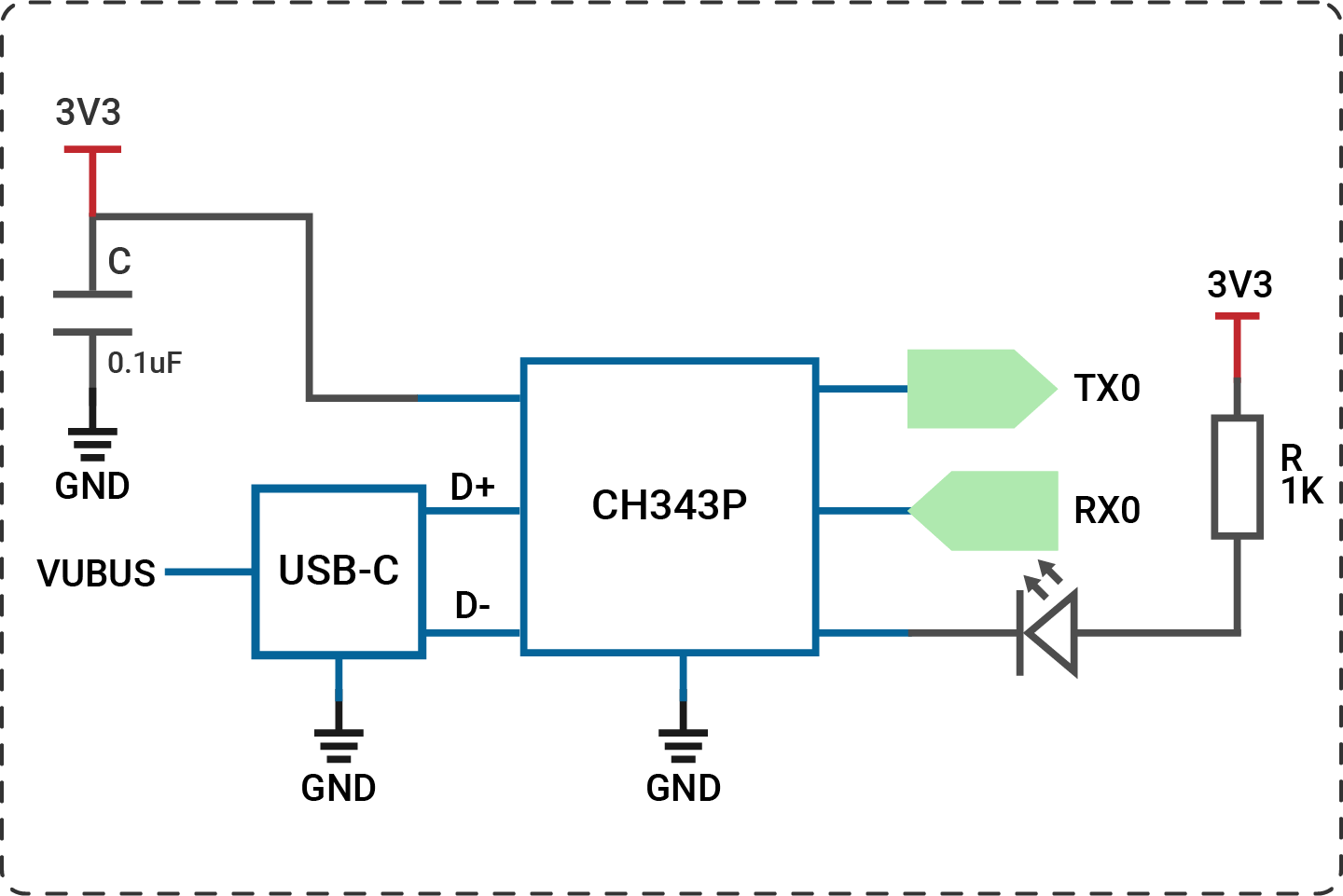
🔸New component
USB-Serial converter
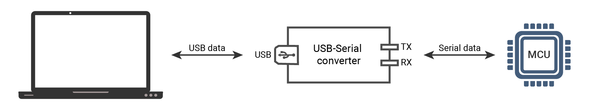
UART is commonly used in embedded systems and other electronic devices. However, many modern computers and devices do not have built-in UART interfaces. This is where the USB-Serial converter comes in.
The USB-Serial converter typically includes a USB connector and a UART interface: it plugs into a USB port on the host device (e.g. a computer) and the UART interface is connected to the target device (e.g. a microcontroller). It takes the serial data from a microcontroller and converts it into USB data that can be understood by a computer, and vice versa.
When you connect it to a computer, it appears as a virtual COM port. To use this port, you need to install the appropriate driver for the converter on your computer. The driver allows the computer to recognize the converter and establish a connection between the USB host device and the UART device. Once the driver is installed, the computer can detect and manage the converter as a serial port device.
To monitor the communication between them, a serial monitor program can be used. This program allows you to view the messages transmitted between the two devices and can display the data in various formats, such as ASCII or hexadecimal. It is usually used in embedded systems development to debug and troubleshoot communication between devices.
The SwiftIO Micro also has a built-in USB-Serial converter. Therefore, you can connect the board directly to your computer via USB and communicate with it over a serial port.
🔸New concept
ASCII
Computers store data in binary format using 1s and 0s. For example, the decimal number 10 is represented as 0b1010. How about the letter "A"? Well, that's where character encoding schemes come into play, and one commonly used one is ASCII (American Standard Code for Information Interchange).
ASCII uses a 7-bit binary code to represent 128 characters, including letters, numbers, and symbols. Taking the word "HELLO" as an example:
| Letter | Decimal | Hexadecimal | Binary |
|---|---|---|---|
| H | 72 | 0x48 | 0b01001000 |
| E | 69 | 0x45 | 0b01000101 |
| L | 76 | 0x4C | 0b01001100 |
| L | 76 | 0x4C | 0b01001100 |
| O | 79 | 0x4F | 0b01001111 |
As shown in the table, these letters can thus be represented in binary format on computers. By referring to the ASCII table, computers can seamlessly decode and interpret these binary representations into the corresponding letters.
In computer systems, numerical values and strings of numbers can indeed be stored differently.
Numerical values are typically stored using specific data types that directly represent the value as a binary representation. For example, the UInt8 value of 1 is stored as 0x01.
On the other hand, strings of numbers are treated as sequences of characters and encoded using a character encoding scheme. The string "1" is represented as the byte 0x31 in ASCII.
Unicode
While ASCII is sufficient for basic English characters, digits, punctuation marks, and some special characters, it falls short when representing characters from non-English languages, like Latin, Cyrillic, Chinese, Arabic, etc.
Unicode was created to address this limitation. It assigns a unique code point to each character, as its identifier. It allows for consistent representation and exchange of text across different platforms, applications, and languages.
For example,
- the emoji "😀" is encoded as U+1F600 (128512 in decimal).
- the Chinese character "你" (which means you) is represented in Unicode as U+4F60 (20320 in decimal).
Unicode can be regarded as a superset of ASCII. The numbers 0-127 in ASCII have the same meaning and representation in Unicode.
Thanks to Unicode, computers can now store and process a vast array of characters from various languages and scripts.
UTF-8, UTF-16, UTF-32
Unicode characters require up to 21 bits to represent all existing characters. In practice, encoding schemes like UTF-8, UTF-16, and UTF-32 were designed to accommodate various considerations.
- UTF-32 uses a fixed 4 bytes to represent each Unicode character, ensuring a straightforward encoding scheme but potentially leading to wasted space for characters with smaller code points.
- UTF-16 uses 2 or 4 bytes to represent characters based on their code points.
- UTF-8 uses 1-4 bytes to represent characters based on their code points. It is specifically designed to be space-efficient, particularly for text that primarily consists of ASCII characters. ASCII characters are represented using a single byte (8 bits), while characters outside the ASCII range require more bytes.
Different encoding schemes interpret and represent characters differently. Therefore, to properly decode text, it is essential to know the specific encoding scheme that was used to encode it.