Potentiometer
You have learned a lot about digital signals and tried many projects with digital devices. Now let's know something about analog signals. The potentiometer is a typical component to give you analog readings. You'll connect a potentiometer to your circuit and read analog values.
Learning goals
- Learn about analog signals and distinguish them from digital signals.
- Learn how ADC works.
- Understand the working principle of potentiometers.
- Learn how the voltage divider works in circuits.
- Use the serial monitor to view printed values.
🔸Circuit - Potentiometer
There are two potentiometers on your SwiftIO Playground. They are connected respectively to A0 and A11.
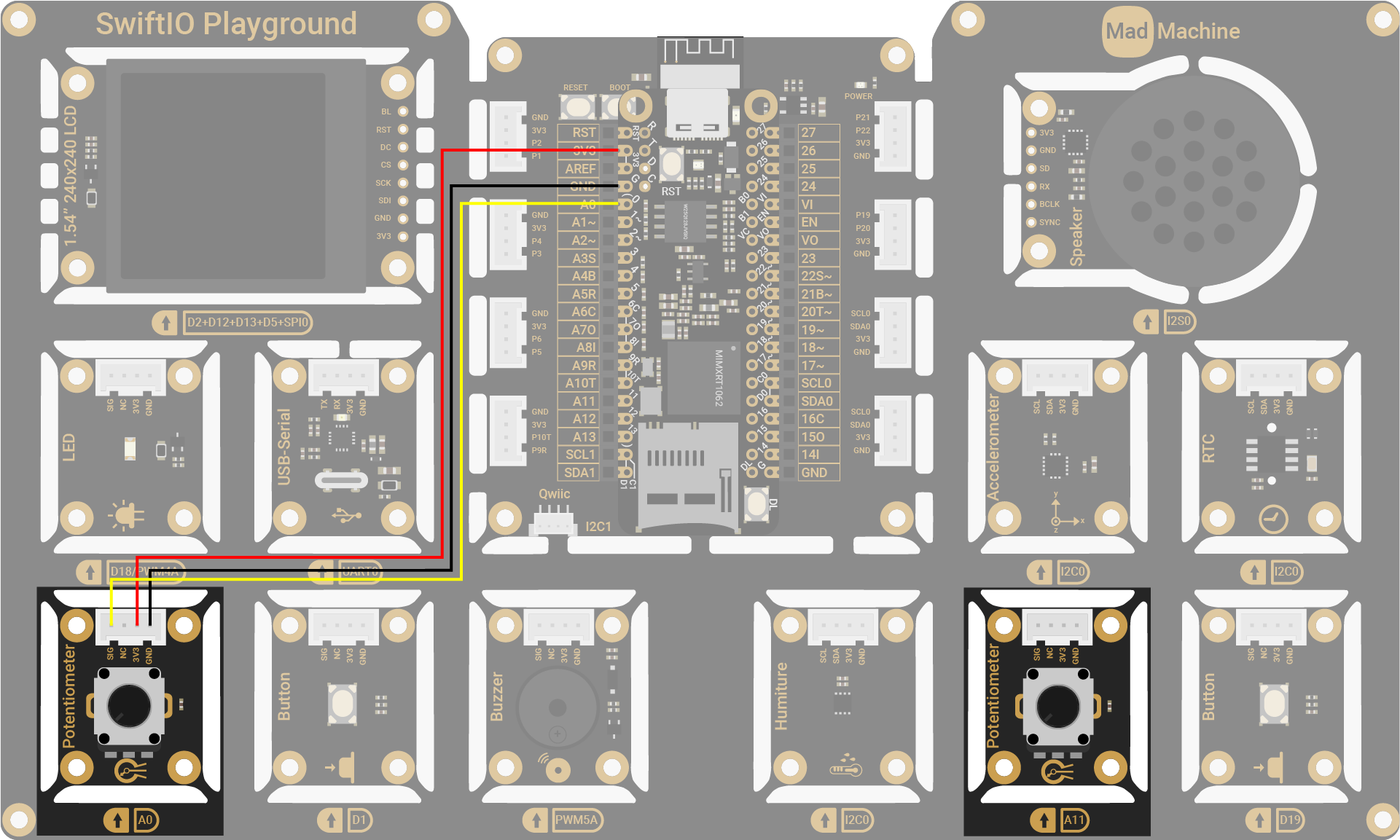
| Potentiometer Pin | SwiftIO Micro Pin |
|---|---|
| SIG | A0 |
| NC (Not Connected) | - |
| 3V3 | 3V3 |
| GND | GND |
The circuits above are simplified for your reference. Download the schematics here.
🔸Projects
1. Reading input
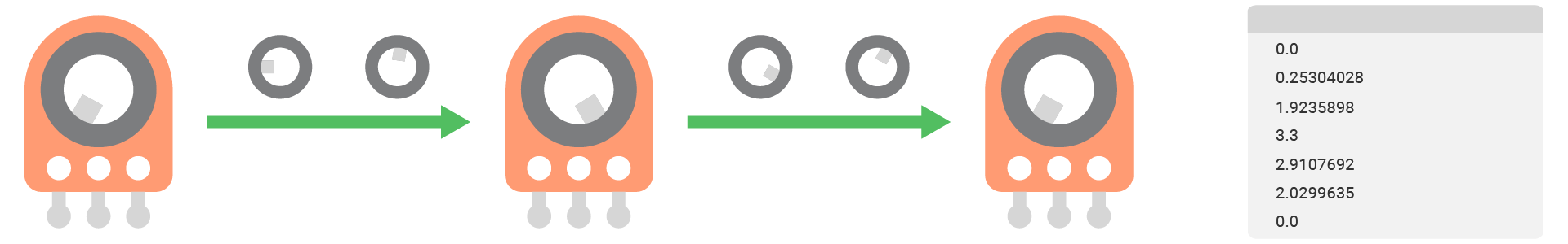
In this project, you will rotate the potentiometer to change the input value. You will view the voltage value on the serial monitor.
Project overview
- After you download the code and connect the port to the serial monitor, the value is printed on the window one by one per second.
- When you turn the potentiometer, the value changes. It gradually goes to the maximum or minimum value according to the direction you twist.
Example code
You can download the project source code here.
// Import SwiftIO library to control input and output, and MadBoard to use the pin name.
import SwiftIO
import MadBoard


// Initialize the analog pin A0 for the potentiometer.
let pot = AnalogIn(Id.A0)

// Read the voltage value and print it out every second.
while true {
    let potVoltage = pot.readVoltage()
    print(potVoltage)
    sleep(ms: 1000)
}
Code analysis
let potVoltage = knob.readVoltage()
Declare a constant to store the returned voltage value.
There are three different methods in AnalogIn class to read analog input. The only difference is the forms of the return value: raw value, voltage value, or percentage. The method readVoltage() returns the voltage reading.
How to use the serial monitor?
- After finishing downloading the project, click SERIAL MONITOR tab.
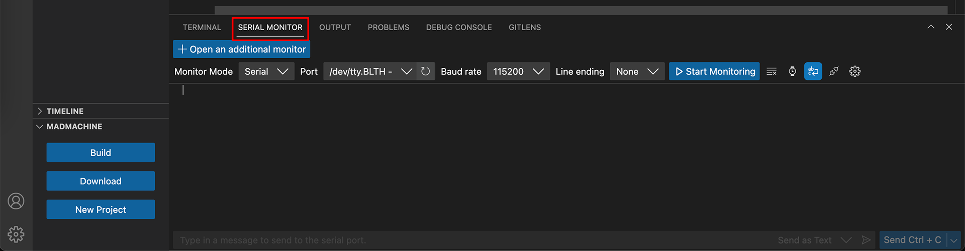
- Choose the port of your board. Its name should start with tty.wchusbserial.
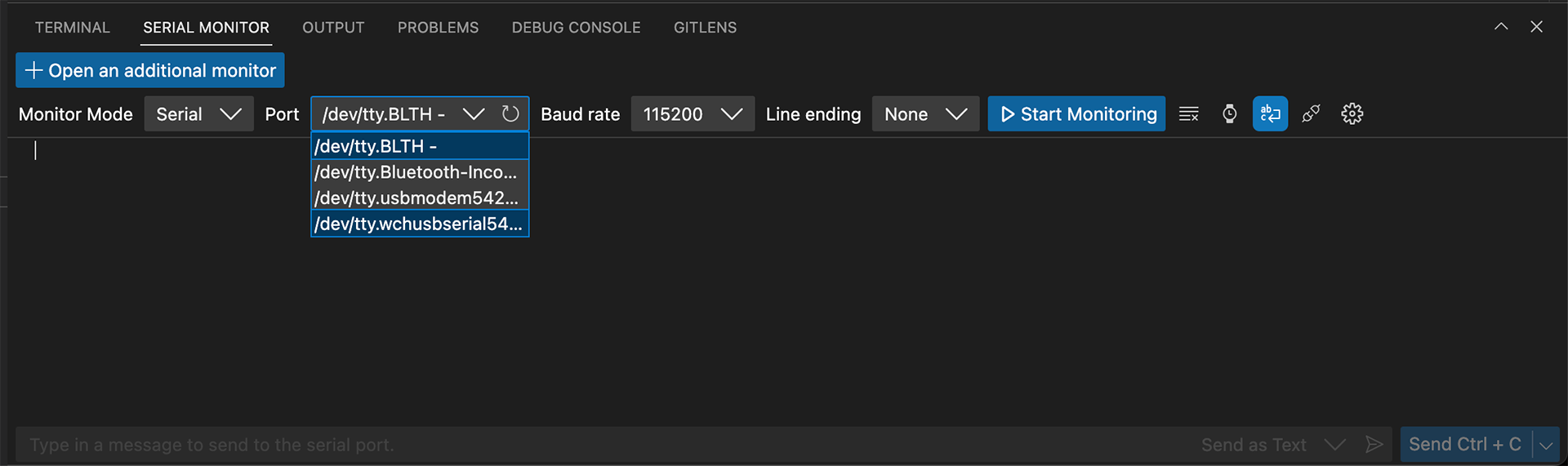
- Select the baudrate 115200.
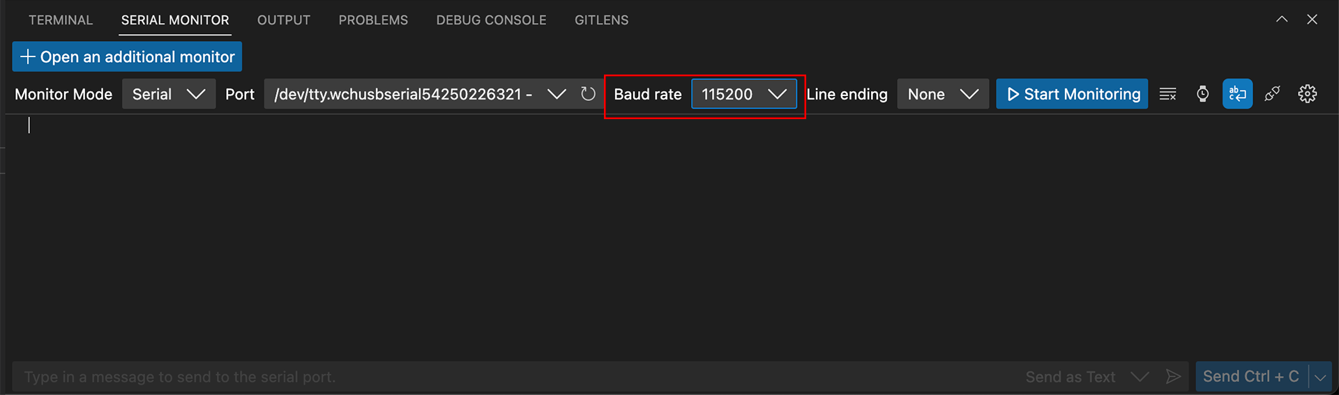
- Click the button Start Monitoring.
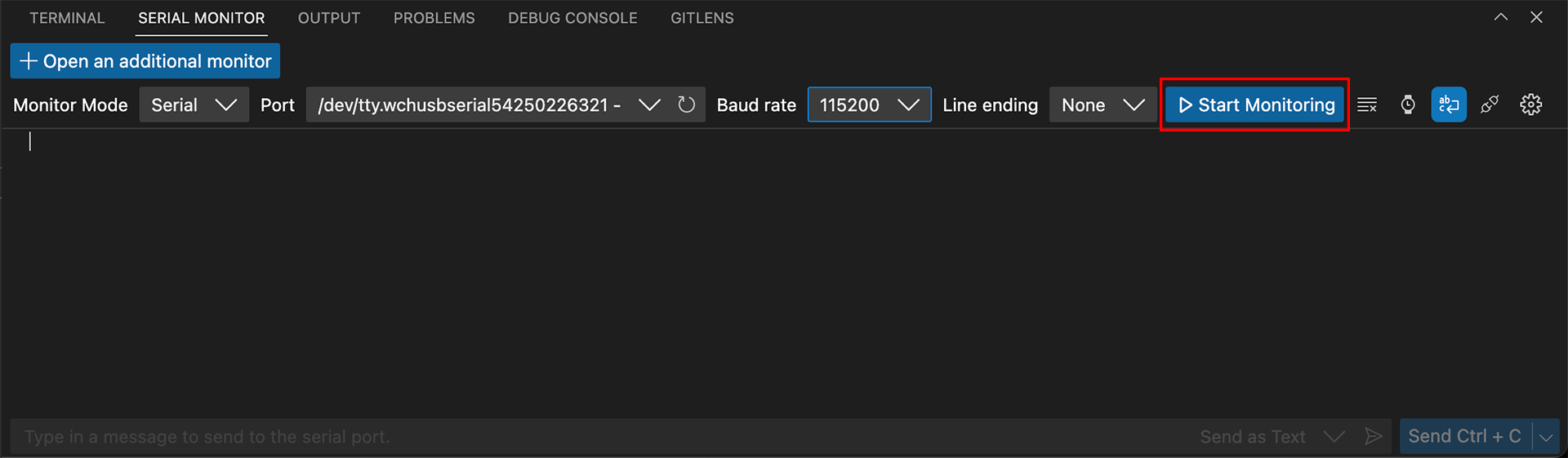
And then you should see the values printed one after another.
Before you download your project to the board, make sure to disconnect the port.
2. Pitch control
You will use a potentiometer to control the sound from the buzzer.
Project overview
- Read the analog value from the potentiometer in percentage.
- Set the PWM frequency based on the value.
- Therefore, the pitch becomes higher when you turn it clockwise and lower when you turn it anticlockwise.
Example code
You can download the project source code here.
// Import the SwiftIO to control input and output and the MadBoard to use the pin name.
import SwiftIO
import MadBoard


// Initialize the analog pin for the potentiometer and PWM pin for the LED.
let pot = AnalogIn(Id.A0)
let buzzer = PWMOut(Id.PWM5A)

// Read the input value in percentage.
// Then calculate the value into the frequency.
// Set the PWM with the frequency and a duty cycle.
while true {
    let potPercentage = pot.readPercentage()
    let frequency = 50 + Int(1000 * potPercentage)
    buzzer.set(frequency: frequency, dutycycle: 0.5)
    sleep(ms: 20)
}
Code analysis
let potPercentage = pot.readPercentage()
Here you use another method readPercentage() to get the input value represented as a percentage.
let frequency = 50 + Int(1000 * potPercentage)
The reading value is too small to serve as frequencies. You then map it to a bigger value to get a frequency from 50 to 1050.
buzzer.set(frequency: frequency, dutycycle: 0.5)
The PWM pins will output signals with the specified frequency to drive the buzzer. In this way, when you turn the potentiometer, the buzzer pitch will change gradually.
3. LED dimmer
The potentiometer can also be used to change LED brightness. In this project, you'll turn the potentiometer to brighten and dim an LED.
Project overview
- Read the analog value from the potentiometer in percentage.
- Set the PWM duty cycle using this value.
- Therefore, the LED becomes brighter when you turn it clockwise and dimmer when you turn it anticlockwise.
Example code
You can download the project source code here.
// Import SwiftIO library to control input and output, and MadBoard to use the pin name.
import SwiftIO
import MadBoard


// Initialize the analog pin for the potentiometer and PWM pin for the LED.
let pot = AnalogIn(Id.A0)
let led = PWMOut(Id.PWM4A)

// Read the input value.
// The value is represented in percentage, while the duty cycle is also between 0 and 1,
// so you can directly use the reading value to set the PWM.
while true {
    let dutycycle = pot.readPercentage()
    led.setDutycycle(dutycycle)

    sleep(ms: 20)
}
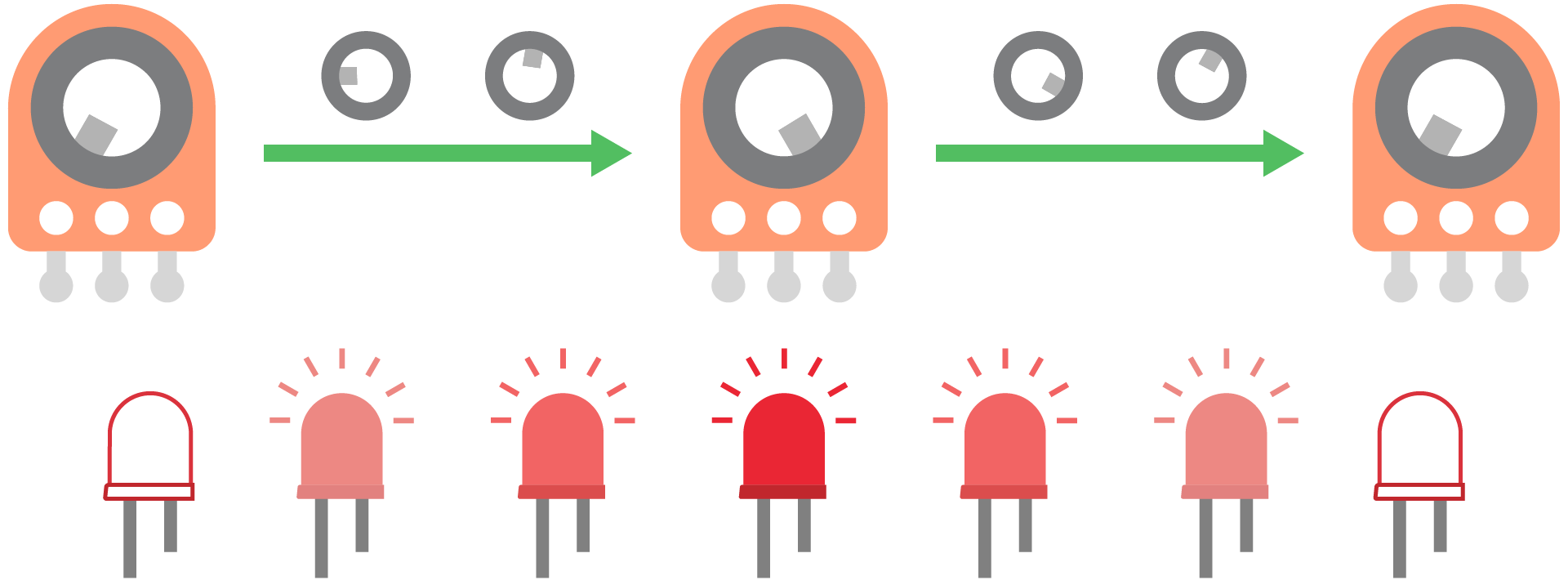
4. LED blink control
Blink the LED. The LED brightness is changed by the potentiometer (A0). The blink rate is changed by the potentiometer (A11).
Project overview
- Read analog value from the potentiometer (A0) in percentage. This value is used to set the duty cycle of the PWM signal, hence it adjusts LED brightness.
- Read raw analog value from the potentiometer (A11). This value sets how long the PWM signal will last, and thus change the LED blink rate.
Example code
You can download the project source code here.
// Use two potentiometers to control LED.
// One changes LED brightness and the other changes the blink rate.

// Import SwiftIO to control input and output.
import SwiftIO
// Import MadBoard to use the pin ids.
import MadBoard


// Initialize the analog pin used to adjust LED brightness.
let brightnessPot = AnalogIn(Id.A0)
// Initialize the analog pin used to change blink rate.
let blinkRatePot = AnalogIn(Id.A11)
// Initialize the PWM pin for the LED.
let led = PWMOut(Id.PWM4A)

while true {
    // Read raw value from the analog pin. It sets the LED blink rate.
    let blinkTime = blinkRatePot.readRawValue() / 2

    // Read value from the analog pin.
    // It serves as duty cycle for PWM to set LED brightness.
    led.setDutycycle(brightnessPot.readPercentage())
    sleep(ms: blinkTime)

    // After a specified time, suspend the output to turn off the LED.
    led.suspend()
    sleep(ms: blinkTime)
}
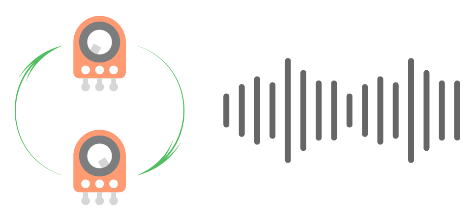
5. Double LED dimmer
In this project, two potentiometers work together to control the LED brightness. One controls the maximum intensity and the other adjusts the brightness between the minimum and the maximum.
Project overview
- Read the analog value for potentiometer A11 in percentage. Map it into a specified maximum duty cycle range, which determines the maximum LED brightness.
- Read the analog value for potentiometer A0 in percentage. It is used to adjust LED brightness between the darkest and the maximum.
- Multiply the two values above to get a final duty cycle.
- Set the PWM signal with the given duty cycle to adjust LED brightness.
Example code
You can download the project source code here.
// In this project, two potentiometers control the LED brightness.
// One controls the maximum intensity and the other adjusts the brightness between the minimum and the maximum.

// Import SwiftIO to control input and output.
import SwiftIO
// Import MadBoard to use the pin ids.
import MadBoard


// Initialize the analog pin used to adjust LED brightness from min and max.
let brightnessPot = AnalogIn(Id.A0)
// Initialize the analog pin used to set max brightness.
let intensityPot = AnalogIn(Id.A11)
// Initialize the PWM pin for the LED.
let led = PWMOut(Id.PWM4A)

// Define the available range of max duty cycle adjusted by A11.
let minIntensity: Float = 0.2
let maxIntensity: Float = 1

while true {
    // Map the analog value from the range 0-1 to the range minIntensity-maxIntensity.
    // It decides the max duty cycle for the PWM signal.
    // That's to say, it changes the maximum intensity of the LED.
    let maxDutycycle = intensityPot.readPercentage() * (maxIntensity - minIntensity) + minIntensity

    // Read the analog value (0-1) from the pin A0 which serves as ratio for final duty cycle.
    let dutycycleRatio = brightnessPot.readPercentage()

    // Calculate the final duty cycle value (0-maxDutycycle).
    // Set the PWM output using the result.
    led.setDutycycle(dutycycleRatio * maxDutycycle)
    sleep(ms: 20)
}
6. Playing tones
Play a scale manually. Rotate the potentiometer to play notes from C4 to C5 one by one.
Project overview
- Store the frequencies of musical notes in an array.
- Read raw analog value from the potentiometer and map it into the index of the array.
- If the new index is different from the last one, set the PWM signal using the corresponding frequency to play the note.
Example code
You can download the project source code here.
// Play scales by rotating a potentiometer slowly.

// Import the SwiftIO library to set the input and output, and the MadBoard to use the pin ids.
import SwiftIO
import MadBoard


// Initialize a PWM pin for the buzzer.
let buzzer = PWMOut(Id.PWM5A)
// Initialize a analog pin for the potentiometer.
let pot = AnalogIn(Id.A0)

// Declare a constant to store an array of frequencies.
// They matches respectively notes C4, D4, E4, F4, G4, A4, B4, C5.
let frequencies = [262, 294, 330, 349, 392, 440, 494, 523]

// Store the last frequency index to avoid playing the same note.
var lastFrequencyIndex = frequencies.count

while true {
    // Read the raw analog value from the pin.
    // Map the value into the index of the array.
    let frequencyIndex = Int((Float(pot.readRawValue() * (frequencies.count - 1)) / Float(pot.maxRawValue)).rounded(.toNearestOrAwayFromZero))

    // Check if the note hasn't been played.
    if frequencyIndex != lastFrequencyIndex {
        // Play the new note for 500ms.
        buzzer.set(frequency: frequencies[frequencyIndex], dutycycle: 0.5)
        sleep(ms: 500)
        buzzer.suspend()
        lastFrequencyIndex = frequencyIndex
    }
    sleep(ms: 10)
}
🔸API
AnalogIn
Read the analog input.
| Method | Explanation |
|---|---|
init(_:) | Initialize an analog pin. Parameter: - idName: the pin id. |
readVoltage() | Read the voltage value on the pin. Return value: A float between 0 and 3.3. |
readPercentage() | Read the input value and represent it as a percentage. Return value: A float between 0 and 1. |
print(_:)
Print out the value which you can view on any serial monitor.
🔸Background
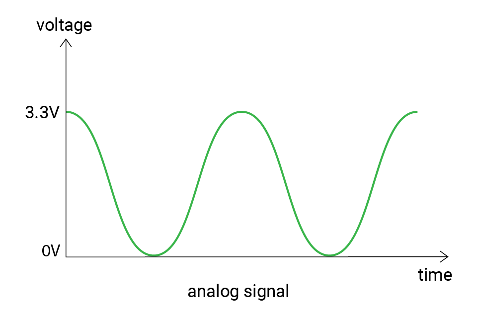
What is an analog signal?
As mentioned before, the signals can be divided into two types: digital signal and analog signal. Unlike the digital signal changing among several values, the analog signal is continuous. Its voltages change smoothly with time, which means there are infinite possible values from minimum to maximum voltage (0 - 3.3V).
Peripheral - ADC
But the microcontrollers are digital components, how do they read the analog voltage at a specific time?
Indeed, the microcontrollers cannot directly read analog values. It needs an analog-to-digital converter (ADC). The ADC works by sampling the analog signal at discrete intervals and then converting the measured voltage to a corresponding digital value that can be processed by the microcontroller. The digital value represents the amplitude of the analog signal at the time it was sampled.
The ability to measure analog values depends on the ADC resolution. The resolution tells the number of possible values. For example, if the resolution is 2-bit, there can be 22 = 4 possible values: 0, 1, 2, 3. These values are called raw values. And if it's 3-bit, there are 23 = 8 values (0-7).
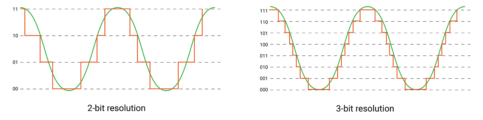
The digital values output by an ADC are often referred to as "raw" values, and they may not be easy to understand or use. To make sense of these values, they need to be mapped back to their corresponding voltage values.
To do this mapping, you need to know the voltage range that the ADC is measuring, 0 to 3.3V in this case. The SwiftIO Micro has a built-in 12-bit ADC, so there are 4096 (212) levels, from 0 to 4095. Therefore, if the raw value equals 0, the voltage would be 0V; if the raw value equals 4095, the voltage would be 3.3V; and 1365 corresponds to (3.3 / 4095) * 1365 = 1.1V.
Here is the equation for the conversion:
voltage = (3.3 / 4095) * raw value
According to the formula, you can infer, higher resolution means more possible values, so the voltage obtained will be more accurate. For instance, if you get a raw value of 6 with a 3-bit ADC, the voltage should be around 3.3 / 7 * 6 ≈ 2.8V. But the same voltage might be considered as 3.3V with a 2-bit ADC.
🔸New component
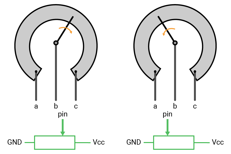
Potentiometer
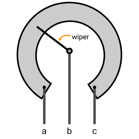
Potentiometer (pot for short, also called knob) is a kind of variable resistor. You can rotate it to change its resistance and thus change the voltage in a circuit. It is commonly used to control the volume on audio devices, as a menu selector knob on home appliances, etc.
The potentiometer has a movable wiper inside it. As you rotate it clockwise or anticlockwise, the wiper moves with it to change the available resistance in the circuit.
Symbols:  (international),
  (US)
(US)
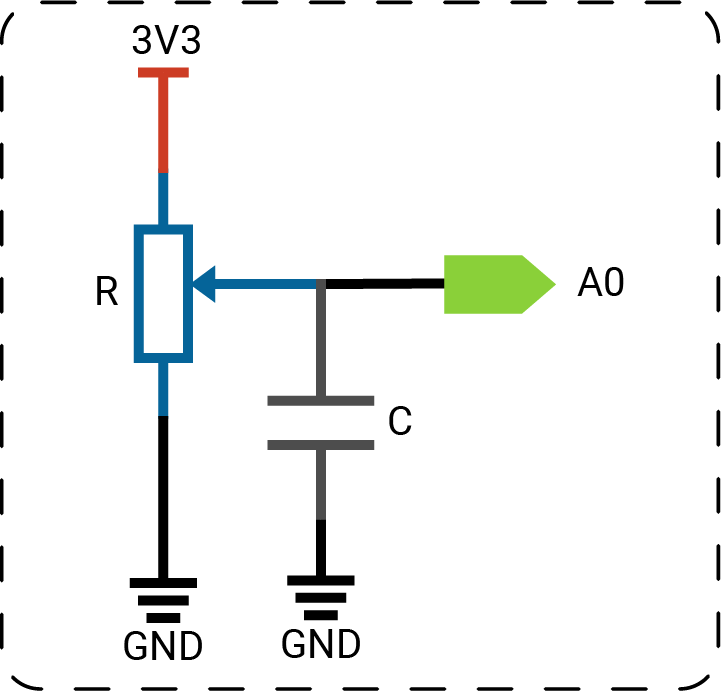
As shown in the image above, it has three terminals. The resistance between two ends (a and c) represents the maximum resistance. The middle one is connected to a wiper. As you rotate the knob, the position of the wiper changes and the resistances on two side of the wiper changes proportionally.
For example, if you connect the outer pin a to the ground, the other outer pin c to power, and the middle pin b to the input pin, let's see how it works.
- When you turn it to make the wiper move gradually far away from a, the actual resistance between a and b in the circuit increases. And the voltage measured on pin b would increase with it, gradually to 3.3V.
- If you turn it in the opposite direction, the voltage on pin b would decrease to 0.
🔸New concept
Voltage divider
A voltage divider circuit is commonly used to get a voltage that is a fraction of the input voltage. Usually, there are resistors connected in series. As the current flows through the resistors, the voltage drops.

The voltage divider calculation is based on ohm's law. Here's the equation:
VR1 = Vin * R1 / (R1 + R2)
Vin: input voltage, VR1: voltage drop on R1
The two resistors are in series, which means the current flows through them are the same, so VR1 / RR1 = Vin / (RR1 + RR2). Then you can get the formula above.
The potentiometer is a typical example of it. The whole resistor is cut into two parts by the wiper. As the wiper goes, the ratio of the resistor changes, thus the voltage drop changes accordingly.