Buzzer and LED with PWM
Now it's time to make some noise🎶.
In this tutorial, you'll work with a new component - buzzer. You'll make it play a scale. Besides, you will adjust LED brightness with PWM signals. Let's figure it out together.
Learning goals
- Clarify the working principle of the PWM signal.
- Know two different types of buzzers: active and passive buzzers.
- Understand how a buzzer produces sound.
- Learn about notes and their frequencies.
- Learn to drive a buzzer with PWM output.
- Learn to adjust LED brightness with PWM output.
🔸Circuit - Buzzer
The buzzer is connected to the pin PWM5A.
The PWM pins are marked with a tilde (~) on the silkscreen of your board. Most of the pins on your SwiftIO Micro are multifunctional. A pin may be used as digital pins and PWM pins. You can refer to this pinout to know the functionalities of each pin.
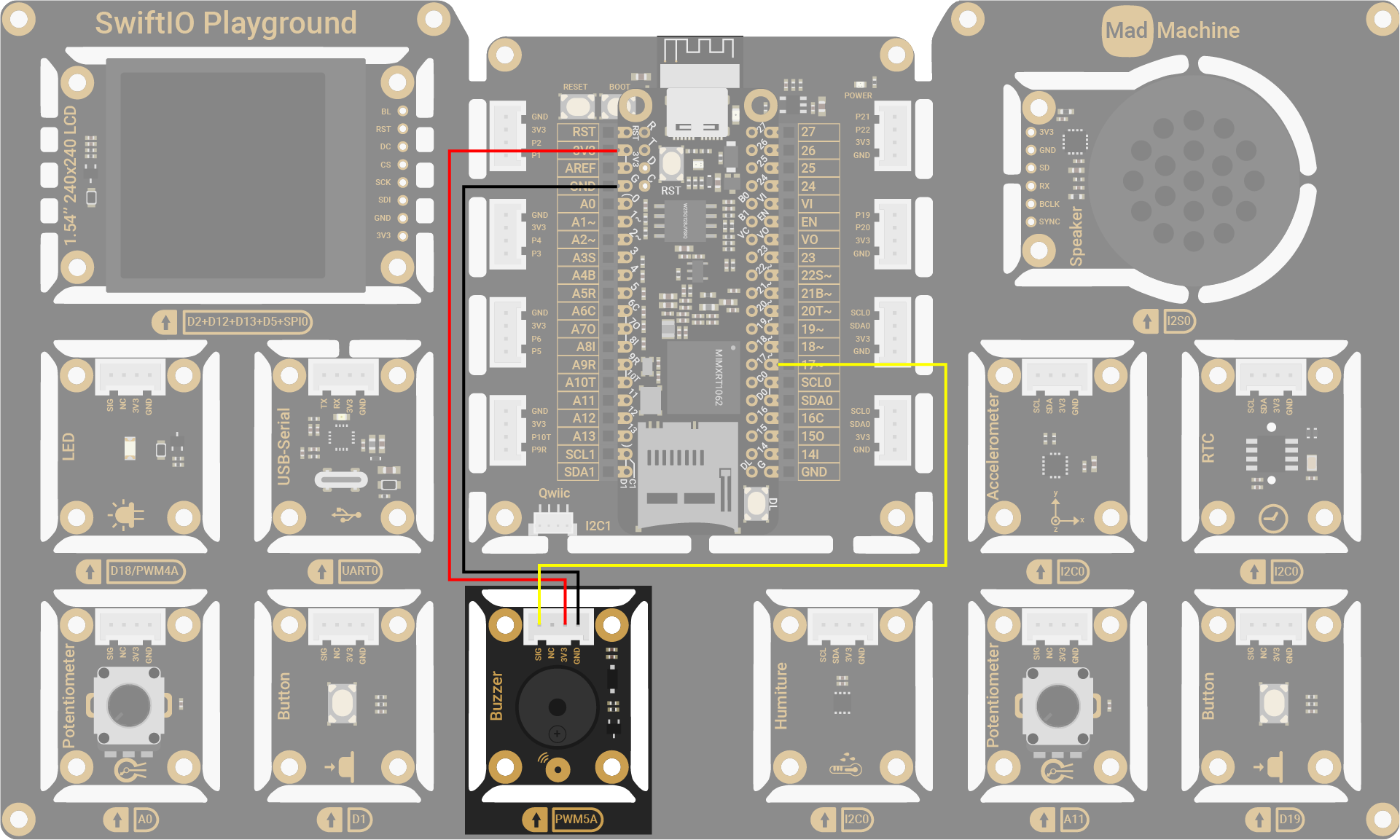
| Buzzer Pin | SwiftIO Micro Pin |
|---|---|
| SIG | PWM5A |
| NC (Not Connected) | - |
| 3V3 | 3V3 |
| GND | GND |
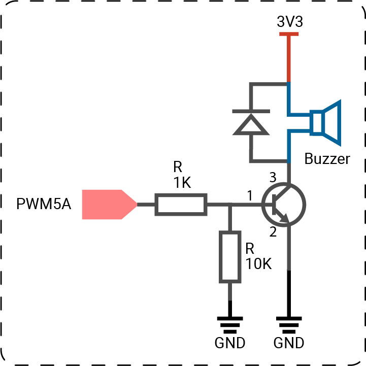
The circuits above are simplified for your reference. Download the schematics here.
🔸Projects
1. Playing a scale
In this project, the buzzer will play the musical scale.
Project overview
- Play the first note C (octave 4) for 1s.
- Similarly, play the following notes: D, E, F, G, A, B, C.
- Stop the sound.
Example code
You can download the project source code here.
// Import the SwiftIO library to set the input and output, and the MadBoard to use the pin id.
import SwiftIO
import MadBoard
// Initialize a PWM pin for the buzzer.
let buzzer = PWMOut(Id.PWM5A)
// Declare a constant to store an array of frequencies.
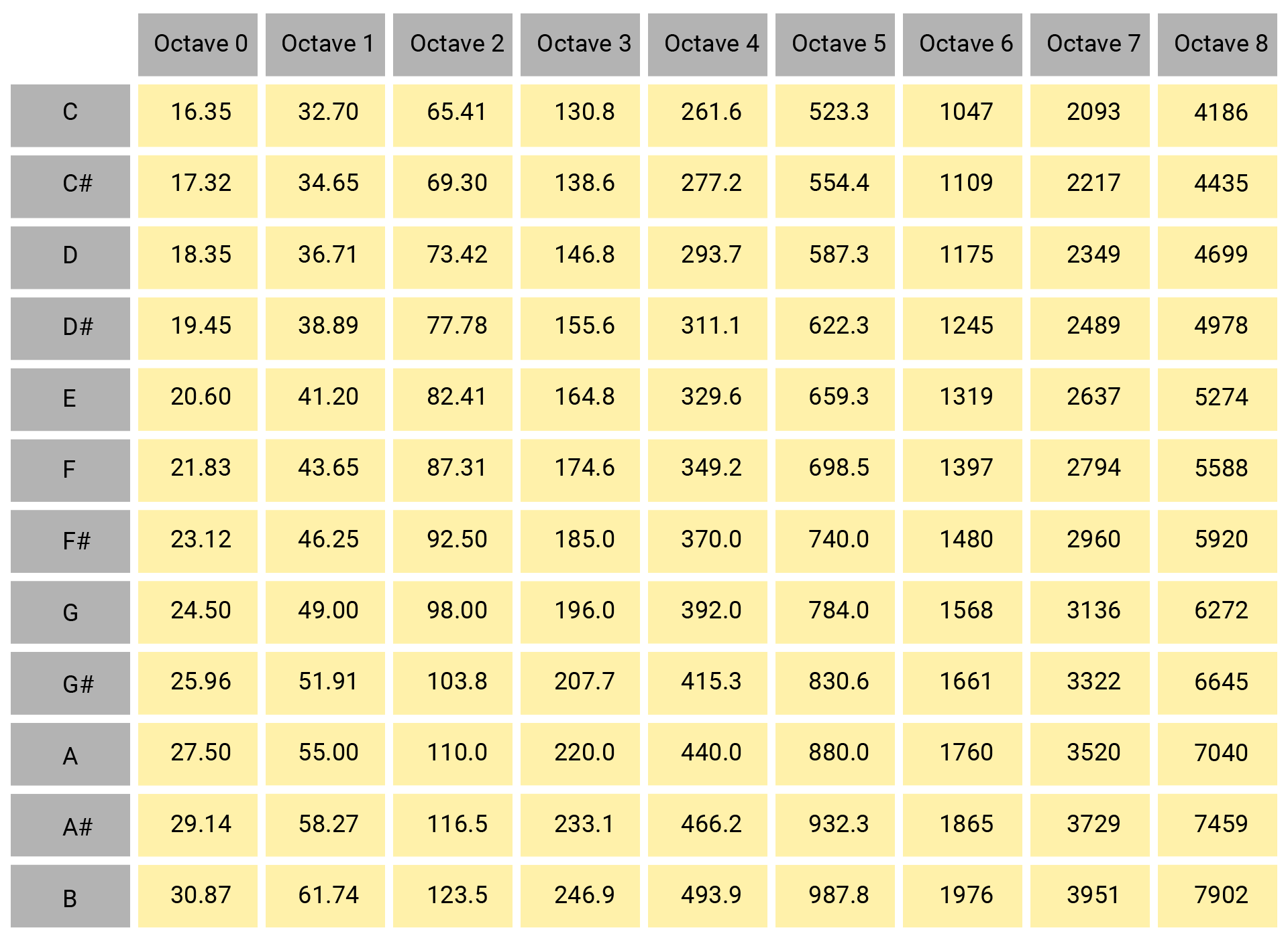
// Consult the pitch-frequency chart above and list all the necessary frequencies in order in the array.
let frequencies = [262, 294, 330, 349, 392, 440, 494, 523]
// Use the for-in loop to iterate through each frequency.
// Set the frequency of the PWM signal to generate sounds. Each note will last 1s.
for frequency in frequencies {
buzzer.set(frequency: frequency, dutycycle: 0.5)
sleep(ms: 1000)
}
// Stop the buzzer sound.
buzzer.suspend()
while true {
sleep(ms: 1000)
}
Code analysis
let frequencies = [262, 294, 330, 349, 392, 440, 494, 523]
Create an array to store the frequencies of each note from C (octave 4) to C (octave 5).
for frequency in frequencies {

}
Iterate through each frequency in the array frequencies using for-in loop.
buzzer.set(frequency: frequency, dutycycle: 0.5)
Set the frequency of the PWM signal. The frequency corresponds to the values in the array frequencies. And the duty cycle can be a float number between 0.0 and 1.0.
buzzer.suspend()
Suspend the PWM output, thus stopping the sound from the buzzer. If you remove this statement, the last note C will last forever.
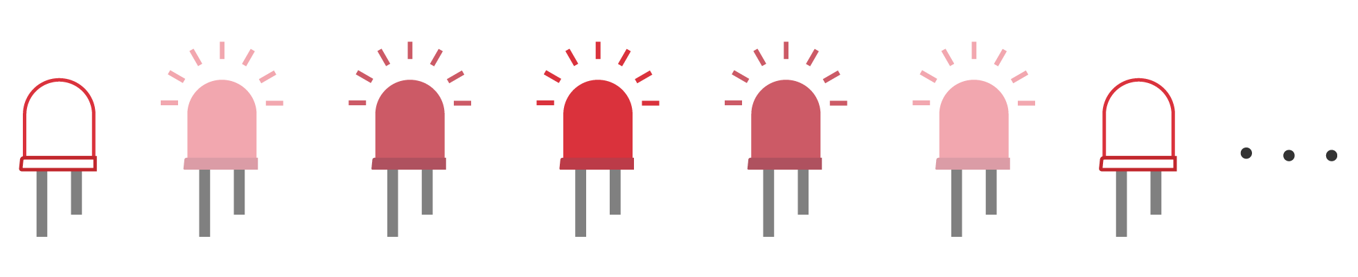
2. Breathing LED
After the musical scale with the buzzer, let's go back to the LED again.
The PWM signal can not only drive a buzzer but also change LED brightness. By applying PWM output, the LED changes between on and off quickly. These on-off changes are invisible to your eyes, so it seems the LED becomes brighter and dimmer. BTW, your monitor may also use this method to control the backlight. A bigger duty cycle will make the LED brighter since the time for high levels is much longer.
So let's try a breathing LED! You may notice it when a new message comes on your phone. The LED changes from the darkest to the brightest, from brightest to darkest smoothly. It looks like it's breathing.
Project overview
- During the first 10ms, the LED is off due to a PWM with 0 duty cycle.
- Every 10ms, gradually increase the duty cycle of the PWM signal to brighten the LED.
- When the duty cycle reaches its maximum, that is, the LED is at the maximum brightness, start to decrease the duty cycle.
- Every 10ms, gradually decrease the duty cycle of the PWM signal to dim the LED.
- When the duty cycle equals/is below its minimum, that is, the LED is at the minimum brightness, start to increase the duty cycle.
Example code
You can download the project source code here.
// Import the SwiftIO library to set the input and output and the MadBoard to use the pin id.
import SwiftIO
import MadBoard


// Initialize a PWM output pin for the LED.
let led = PWMOut(Id.PWM4A)

// Store the maximum and minimum values of the duty cycle to two constants.
let maxDutycycle: Float = 1.0
let minDutycycle: Float = 0.0

// Set the change of duty cycle for each action.
let stepDutycycle: Float = 0.01

// Create a variable to store the varying duty cycle.
var dutycycle: Float = 0.0

// A condition used to decide whether to increase or decrease the duty cycle.
var upDirection = true

while true {
    // Output a PWM signal with the specified duty cycle to control LED brightness.
    led.setDutycycle(dutycycle)
    // Keep each brightness last for 10ms, or you may not see the changes.
    sleep(ms: 10)

    // Increase or decrease the duty cycle within its range according to the value of upDirection.
    if upDirection {
        dutycycle += stepDutycycle
        if dutycycle >= maxDutycycle {
            upDirection = false
            dutycycle = maxDutycycle
        }
    } else {
        dutycycle -= stepDutycycle
        if dutycycle <= minDutycycle {
            upDirection = true
            dutycycle = minDutycycle
        }
    }
}
Code analysis
let maxDutycycle: Float = 1.0
let minDutycycle: Float = 0.0
let stepDutycycle: Float = 0.01
There are some built-in data types in the Swift language, like Int (integer), Float and Double (decimal number), Bool (true and false), etc. Each type corresponds to different values type and value range. If the values in your program don't match or exceed the default range, the compilation will fail.
Besides, if you don't explicitly declare the data type, Swift will use type inference to decide the type. For example, if the minDutycycle is written as 0, Swift would judge it as an Int. When dealing with decimal numbers 0.0, it can be either float or double. The default choice of Swift is double. However, the duty cycle used in PWMOut class is Float. Therefore, the values above need to be explicitly declared as Float.
The LED brightness depends on the duty cycle of the PWM signal. The duty cycle is always between 0 and 1. So the maximum and minimum values are stored in two constants for later comparison.
The constant stepDutycycle is the change of the duty cycle. You'll increase and decrease the duty cycle by the value repeatedly. Make sure stepDutycycle is not too big so the brightness changes smoothly.
var dutycycle: Float = 0.0
The LED brightness changes with the duty cycle of the PWM signal. So this variable stores the latest duty cycle to set the PWM.
var upDirection = true
This variable is used as a condition to decide whether the LED will become brighter or dimmer. In the beginning, it's true so the LED will become brighter.
led.setDutycycle(dutycycle)
Set the duty cycle of PWM output to adjust LED brightness.
sleep(ms: 10)
It makes each brightness last for 10ms. If you remove this statement, the LED changes so fast that you cannot notice the brightness change.
The duty cycle is 0 - 1, and the change is 0.01 each time. So one loop will last about 100 times. Then let's suppose the LED changes from darkest to full brightness in 1 second, and you will get the duration for each state - 10ms.
if upDirection {

} else {

}
This conditional statement decides how the duty cycle will change according to upDirection.
-
If it's
true, the duty cycle will increase by the value ofstepDutycle. Once its value exceeds the maximum,upDirectionwill befalse. -
If it's
false, the duty cycle will decrease. When it is below its minimum,upDirectionbecomestrue.
dutycycle += stepDutycycle
+= combines the addition and assignment. It equals dutycycle = dutycycle + stepDutycycle.
Similarly, -= means dutycycle = dutycycle - stepDutycycle.
if dutycycle >= maxDutycycle {
    upDirection = false
    dutycycle = maxDutycycle
}
This statement is to know whether the duty cycle exceeds its range. If so, upDirection is changed to false. In the next loop, the duty cycle will begin to decrease by stepDutycycle.
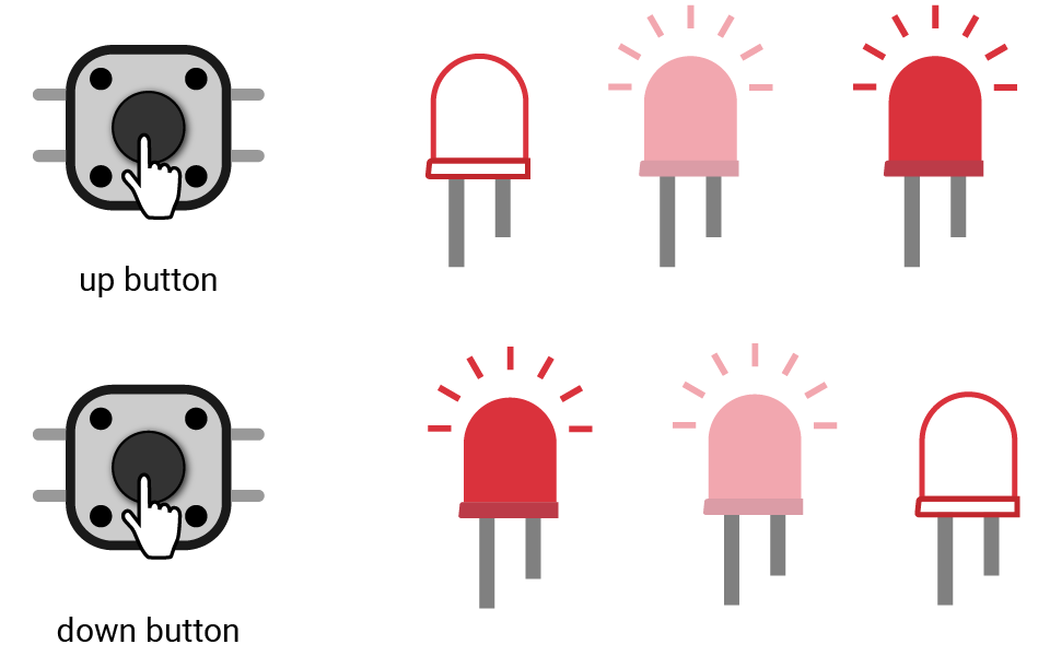
3. Button dimmer
You'll adjust the brightness of the LED using two buttons: one is reserved to increase the brightness, the other is to reduce the brightness.
Project overview
- Detect if any of the buttons are pressed.
- If detected, update the duty cycle. A press of up button (D19) will increase its value while a press of down button (D1) will decrease it.
- Set the PWM signal with the new duty cycle to adjust LED brightness.
Example code
You can download the project source code here.
// Import the SwiftIO library to set the input and output and the MadBoard to use the pin id.
import SwiftIO
import MadBoard


// Initialize the PWM pin.
let led = PWMOut(Id.PWM4A)

// Store the max and min values of duty cycle to two constants.
let maxDutycycle: Float = 1.0
let minDutycycle: Float = 0.0

// The variation of duty cycle per button press.
let stepDutycycle: Float = 0.1

// Create a variable to store the value of duty cycle.
var dutycycle: Float = 0.0

// Initialize the digital pins. downButton is to dim the LED and the upButton is to brighten the LED.
let downButton = DigitalIn(Id.D1)
let upButton = DigitalIn(Id.D19)

var dutycycleChanged = false

// Each time this button is pressed, the LED will dim a little until it reaches the minimum brightness.
downButton.setInterrupt(.rising) {
    dutycycle -= stepDutycycle
    dutycycle = max(dutycycle, minDutycycle)
    dutycycleChanged = true
}

// Once this button is pressed, the LED becomes brighter until it reaches the maximum brightness.
upButton.setInterrupt(.rising) {
    dutycycle += stepDutycycle
    dutycycle = min(dutycycle, maxDutycycle)
    dutycycleChanged = true
}

// Update the duty cycle of PWM signal to change the LED brightness.
while true {
    if dutycycleChanged {
        led.setDutycycle(dutycycle)
        dutycycleChanged = false
    }
    sleep(ms: 10)
}
Code analysis
downButton.setInterrupt(.rising) {
    dutycycle -= stepDutycycle
    dutycycle = max(dutycycle, minDutycycle)
    dutycycleChanged = true
}
The two button upButton and downButton works similarly. Take downButton for example.
You'll use the interrupt mechanism to detect if the button is pressed. There are three statements for the interrupt. Each of them can be executed in a very short time and thus can be used as ISR.
max() is used to get the biggest one between the values. In this way, even if the result of the calculation is smaller than its minimum (0.0), the duty cycle is still 0.0 to keep the LED at the minimum brightness.
4. Reflex game
In this project, let's test the reflex time.
Project overview
- Press the button D1 to start the game. You'll hear a beep from the buzzer as a notification.
- Once you see the red LED turns on, press the button D19 immediately.
- Then the LED turns off and you can see your reflex time printed on a serial monitor.
- To restart the game, press button D1 again.
Example code
You can download the project source code here.
// Press the button D1 to start the game.
// Once you see the red LED turns on, press the button D19 immediately.
// Then the LED turns off and you can see your reflex time in serial monitor.
// To restart the game, press button D1 again.

import SwiftIO
import MadBoard


let startButton = DigitalIn(Id.D1)
let player = DigitalIn(Id.D19)
let buzzer = PWMOut(Id.PWM5A)
let led = DigitalOut(Id.D18)

while true {
    // Press the start button to begin the game.
    if startButton.read() {
        // A beep as a notification.
        buzzer.set(frequency: 500, dutycycle: 0.5)
        sleep(ms: 500)
        buzzer.suspend()

        // Wait for several seconds before the game starts.
        sleep(ms: 1000 * Int.random(in: 1...5))

        // Turn on the red LED as a sign of start.
        led.high()
        // Store the current clock cycle.
        let startClockCycle = getClockCycle()

        // Wait until the button is pressed.
        while !player.read() {
            sleep(ms: 1)
        }

        // Calculate the time in ns.
        let duration = cyclesToNanoseconds(start: startClockCycle, stop: getClockCycle())
        // Turn off the indicator.
        led.low()
        print("Reflex time: \(Float(duration) / 1000_000)ms")
    }

    sleep(ms: 10)
}
Code analysis
let startClockCycle = getClockCycle()
let duration = cyclesToNanoseconds(start: startClockCycle, stop: getClockCycle())
The two functions are used together to measure a short period (a few seconds) with precision.
getClockCycle() gets the current time stamp in clock cycles. The duration of a cycle is determined by the CPU frequency. This value is from a 32-bit register driven by the CPU frequency and will overflow every few seconds.
cyclesToNanoseconds() calculates the passed time in nanoseconds using a start time and stop time.
print("Reflex time: \(Float(duration) / 1000_000)ms")
It allows you to see the value on a serial monitor.
It is a useful tool to debug your code if there is something unexpected in your program. You could add it after each statement that changes a value. Then you could infer which step goes wrong according to the printed results.
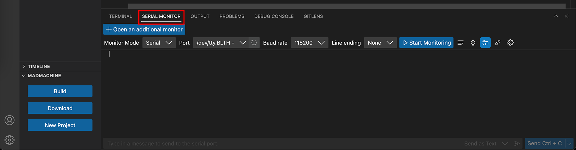
How to use the serial monitor?
- After finishing downloading the project, click SERIAL MONITOR tab.
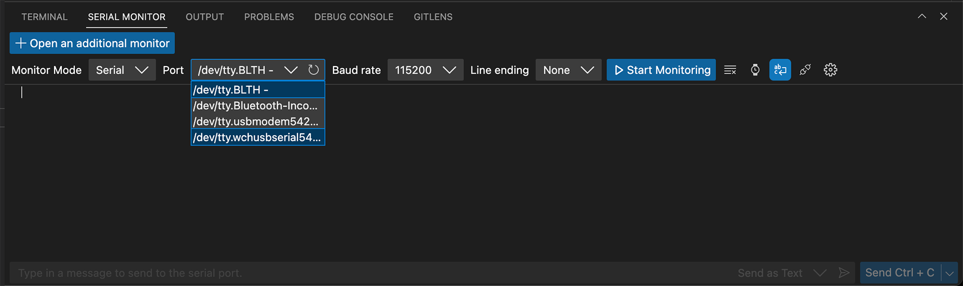
- Choose the port of your board. Its name should start with tty.wchusbserial.
- Select the baudrate 115200.
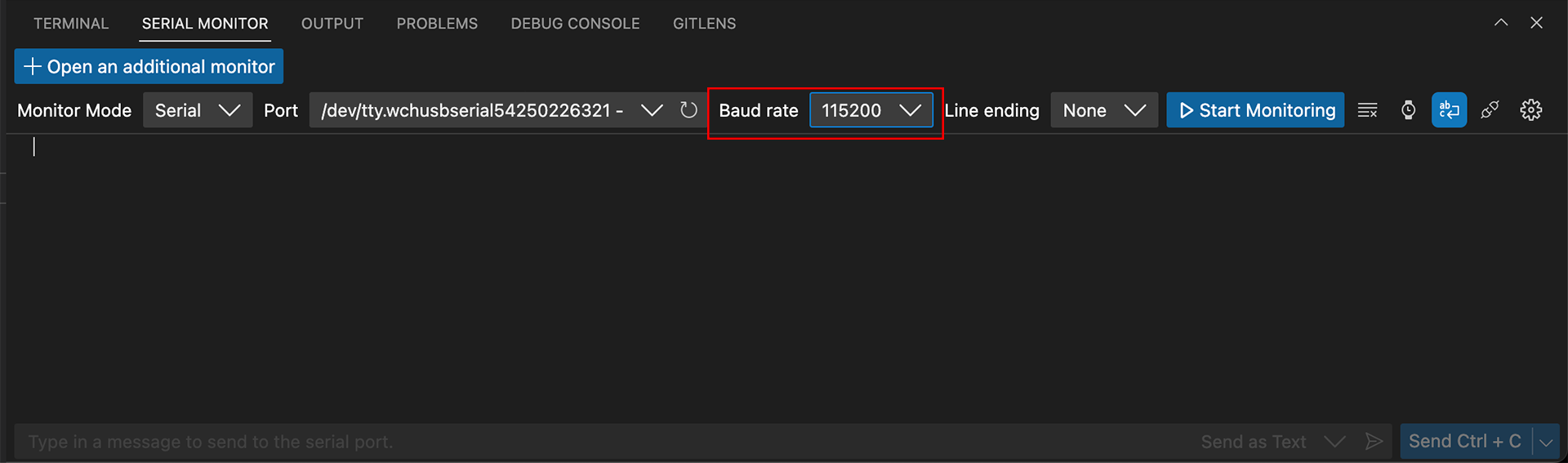
- Click the button Start Monitoring.
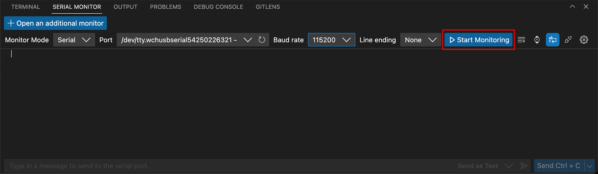
And then you should see the values printed one after another.
Before you download your project to the board, make sure to disconnect the port.
5. LED pattern change
Many types of light decorations, such as Christmas lights or string lights, often have different lighting patterns that can be accessed by pressing a button or switch. In this project, let's reproduce it!
Project overview
- In the beginning, the LED stays off.
- If you press the button once, the LED turns on.
- If the button is pressed again, the LED starts to blink.
- If the button is pressed again, the LED starts breathing.
- If the button is pressed again, the LED turns off.
Example code
You can download the project source code here.
// Switch the LED pattern by pressing the button.
// The LED patterns are constant off, constant on, blink, breathing.

import SwiftIO
import MadBoard


let led = PWMOut(Id.PWM4A)
let button = DigitalIn(Id.D1)

// Store the maximum and minimum values of the duty cycle to two constants.
let maxDutycycle: Float = 1.0
let minDutycycle: Float = 0.0

var dutycycle: Float = 0.0
var stepDutycycle: Float = 0.01

// The duration in ms of each loop.
let loopDuration = 10
// Make the LED on for 500ms and off for 500ms.
let blinkPeriod = 1000
var blinkTime = 0

var patternIndex = 0
var changePattern = false

// Set the duty cycle depending on the pattern.
resetDutycycle()

var buttonPressed = false

// If the button has been pressed and is released now, change to the next pattern.
button.setInterrupt(.falling) {
    buttonPressed = true
}

while true {
    if changePattern {
        // Reset the duty cycle after changing the pattern.
        resetDutycycle()
        changePattern = false
    } else {
        // Update duty cycle depending on the current LED pattern.
        updateDutycycle()
    }

    // Set the PWM with the given duty cycle to change LED brightness.
    led.setDutycycle(dutycycle)
    sleep(ms: loopDuration)

    // Update pattern index after button has been pressed and is released now.
    if buttonPressed {
        changePattern = true
        patternIndex += 1
        if patternIndex == LEDPattern.allCases.count {
            patternIndex = 0
        }

        buttonPressed = false
    }
}

// Reset the duty cycle for a new LED pattern.
func resetDutycycle() {
    switch LEDPattern(rawValue: patternIndex)! {
    case .off:
        dutycycle = minDutycycle
    case .on:
        dutycycle = maxDutycycle
    case .blink:
        dutycycle = maxDutycycle
        blinkTime = 0
    case .breathing:
        dutycycle = minDutycycle
        stepDutycycle = abs(stepDutycycle)
    }
}

// Update the duty cycle of the PWM signal according to the current LED pattern.
func updateDutycycle() {
    switch LEDPattern(rawValue: patternIndex)! {
    case .blink:
        // For the first half of blinkPeriod, turn on the LED.
        // For the second half of blinkPeriod, turn off the LED.
        // The duty cycle changes between 0.0 and 1.0 to turn on and off the LED in turn.
        blinkTime += loopDuration
        dutycycle = blinkTime % blinkPeriod < (blinkPeriod / 2) ? maxDutycycle : minDutycycle
    case .breathing:
        // The duty cycle gradually increases to the maximum, then decrease to the mininum.
        // Therefore, the LED brightens and dims in turn.
        dutycycle += stepDutycycle

        // Check if LED brightness is increaed to the max or decreased to min.
        if stepDutycycle > 0 && dutycycle >= maxDutycycle {
            stepDutycycle.negate()
            dutycycle = maxDutycycle
        } else if stepDutycycle < 0 && dutycycle <= minDutycycle {
            stepDutycycle.negate()
            dutycycle = minDutycycle
        }
    default: break
    }
}

enum LEDPattern: Int, CaseIterable {
    case off
    case on
    case blink
    case breathing
}
Code analysis
In this project, you will control the LED using the PWM signal. The key factor for each pattern is the duty cycle:
| Pattern | Duty cycle |
|---|---|
| off | 0 |
| on | 1 |
| blink | 0 / 1 |
| breathing | 0 - 1 |
So you just need to store the current pattern and update the PWM duty cycle as needed. If the button is pressed, update the stored pattern and change the duty cycle accordingly.
🔸API
PWMOut
This class allows you to set the frequency and duty cycle of PWM output from the board.
| Method | Explanation |
|---|---|
init(_:frequency:dutycycle:) | Initialize a PWM output pin. Parameter: - idName: id of the pin. - frequency: frequency of the PWM signal, 1000Hz by default. - dutycycle: a float representing duty cycle of the PWM, 0 by default. |
set(frequency:dutycycle:) | Set the frequency and duty cycle of the PWM signal. Parameter: - frequency: frequency of the PWM signal. - dutycycle: a float representing duty cycle of the PWM. |
setDutycycle(_:) | Set the duty cycle of the PWM signal. Parameter: - dutycycle: a float representing duty cycle of the PWM. |
suspend() | Suspend the PWM signal. |
🔸Background
What is PWM?
In the previous projects, you tried the digital output to turn on and off an LED. But how can you make the LED dimmer or brighter? Well, the pulse width modulation (PWM) can deal with it. Let's first learn about the PWM.
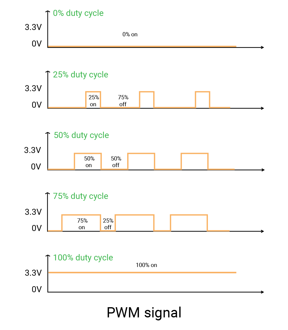
As you know, a digital signal always outputs high or low level. The PWM signal is still a square wave signal with two states: on (when the signal is high) and off (when the signal is low). The on-time of the signal is called pulse width. So as its name suggests, PWM refers to the method of changing the pulse width, that is, the proportion of on-time to control the output. The signal would change extremely quickly between on and off. It's so fast that your eyes can't notice the change. In this way, you seem to get an average voltage between 0V and 3.3V.
Here are some important concepts about PWM:
-
The duty cycle describes the percentage of the on-time in a period:
- 0 means the signal is always low.
- 1 means it is always high.
- A signal with a duty cycle of 0.5 should be high for 50% of the time and low for 50% of the time. And the average voltage is 1.65V.
- So a signal with any duty cycle between 0 and 1 can simulate a voltage between 0 and 3.3V.
-
One period of the signal consists of on-time and off-time. It describes the time that a cycle lasts.
-
The frequency is the inverse of the period. It tells the count of cycles in one second. Take 1000Hz for example, the signal has 1000 cycles per second, and the period is 1ms.

Peripheral - PWM
The PWM peripheral in a microcontroller is designed to generate PWM signals. The PWM pins are typically labeled with a tilde symbol (~) to indicate their capability. These pins can be used to control the speed of motors, the brightness of LEDs...
If you look at the PWM pin names of the SwiftIO Micro, you may find they are marked with A or B at the end. Actually, the PWM pins are grouped in pairs, like PWM2A and PWM2B. The two pins in a group share the same frequency. So if you need two PWM pins with different frequencies, you should use the pins in different groups, like PWM0A and PWM1A.
🔸New component
Buzzer
The buzzer is a kind of audio device to produce beeping and sharp sounds. It is widely used for notification and confirmation. You may hear it from alarms, toys, or when pressing buttons.
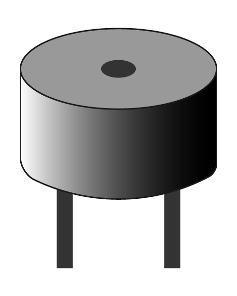
Symbol: 
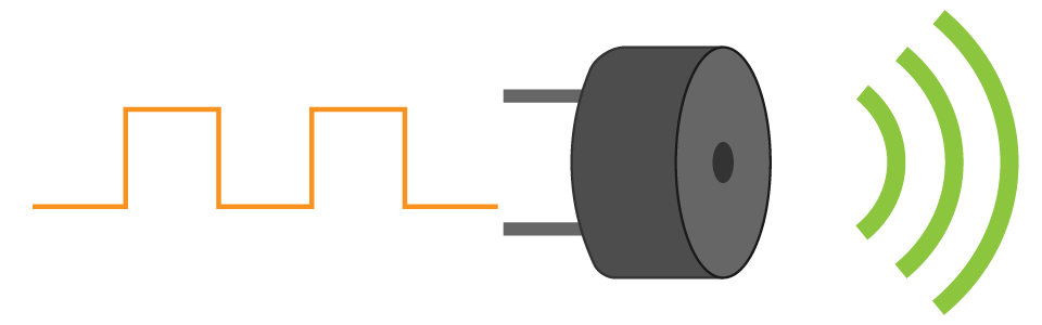
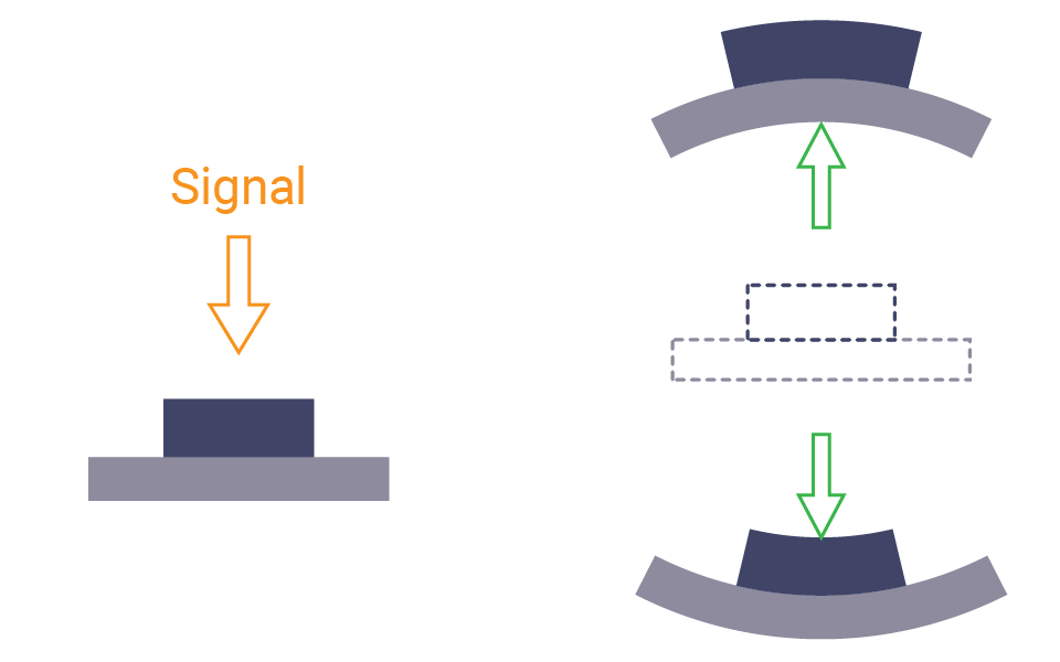
How does it emit the sound? It's due to the diaphragm inside it. As you apply to a buzzer a current that changes with time, the internal diaphragm will vibrate back and forth quickly. The vibration of the diaphragm thus vibrates the surrounding air, hence producing a sound. When there is no current, the diaphragm will go back to its original position, the sound thus stops.
There are two kinds of buzzers:
- The active buzzer contains an internal circuit that can create varying voltage. So once you power this kind of buzzer, it will make a sound automatically. But it can only produce one constant sound since the wave generated by the internal circuit is determined. What's more, the active buzzer is polarised and needs to connect in the right direction.
- The passive buzzer needs a PWM signal to drive it. The pitch of a sound depends on the frequency of the signal. Higher frequency would move the diaphragm faster and lead to a higher pitch. And the one in the kit is a passive buzzer.
They looks alike. To distinguish them, you can connect them to power. If it sounds, it is an active buzzer.
🔸New concept
Pitch
You must be familiar with do, re, mi... They correspond respectively to the note C, D, E, F, G, A, B. Please note the notes start from C but aren't in alphabetical order.
The pitch of each note is decided by the frequency. High pitch corresponds to high frequency, low pitch corresponds to low frequency. The following table gives the frequency of each note. When it comes to Middle C (octave 4), which is the first note to find when you start to learn the piano, the frequency is about 262 Hz.
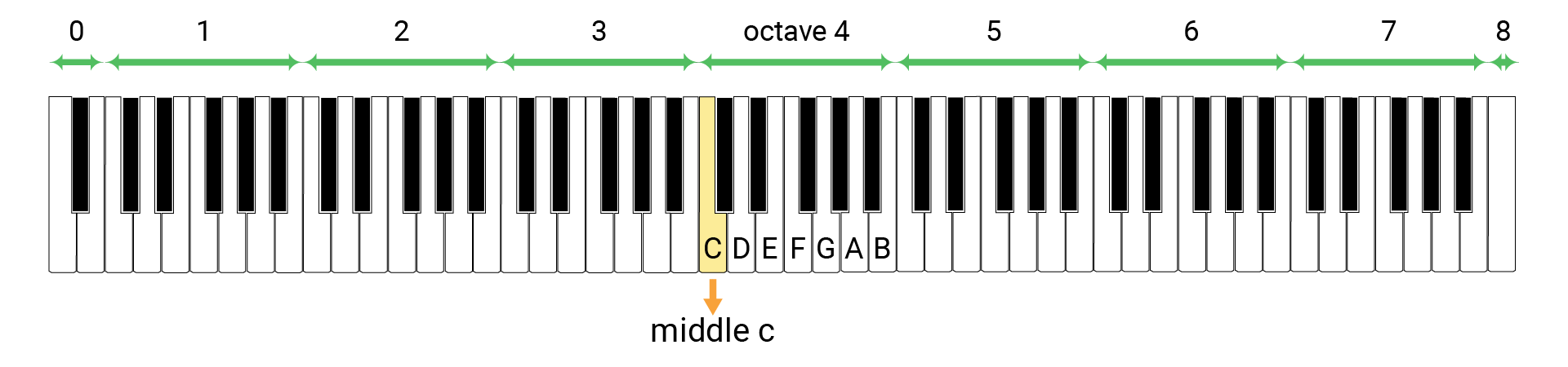
A piano keyboard would be helpful to understand the concept. All keys on the keyboard has a corresponding pitch. They are divided into several octaves.
Let's look at the octave 4 in the middle. The white keys correspond to the notes C, D, E, F, G, A, B. And the note C in this octave is the middle C. The other octave are similar, but will be higher or lower in pitch according to the frequencies.
So to make the buzzer play a piece of melody, you need to find the frequency and set a proper duration for each note according to the score.