Peripherals on MCU
In the previous tutorial, you were introduced to the concept of microcontrollers. An MCU is comprised of several essential components, including a CPU, RAM, ROM, and various peripherals. In this tutorial, you will dive deeper into the subject of peripherals and explore their important role in MCUs.
What are the peripherals on MCU?
Peripherals are additional circuits and components built into the MCUs to perform specific tasks and enhance their capabilities, making them more versatile and efficient. They are typically connected to the CPU through an internal bus.
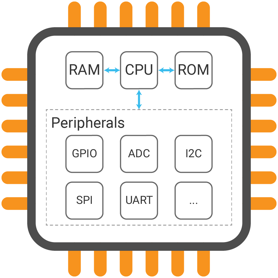
The common peripherals on many MCUs are GPIO, Timer, PWM, ADC, UART, SPI, I2C... For example, GPIO allows the MCU to read and write digital signals and I2C, SPI or UART allows it to communicate with other devices. By using peripherals, the MCU can perform a wide range of work.
Therefore, when you work with an MCU, you typically program the peripherals to do specific tasks. You will dive into them and experiment with different devices in the next section.
How to use/control the peripherals on MCU
MCUs often have reserved memory space for peripherals, called peripheral register, which is used to store the configuration and operating parameters for the peripherals.
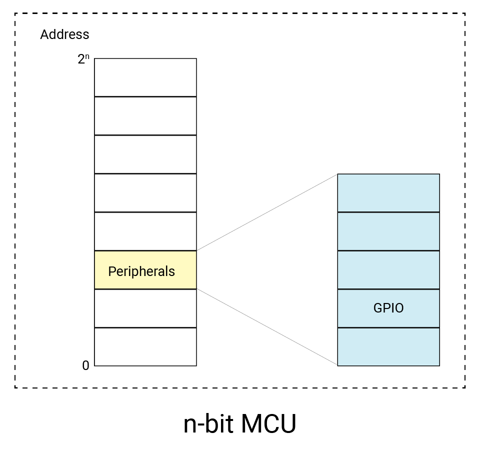
With the memory map technique, each peripheral is assigned a unique address in one unified memory space. The CPU can write and read data to and from its register to access the specified peripheral. In this way, you can use and control the peripherals as needed. Normally, the clock (the operating frequency of the peripheral) and power (whether the peripheral is active or in a low-power state) of each peripheral are required to be configured.
Usually, you do not need to be concerned with the details of how the peripherals are implemented or how to access their internal registers. Instead, you can use the APIs provided by hardware abstraction to control and configure the peripherals in a straightforward manner.
How do peripherals interact with external devices?
MCUs can route their internal peripherals to different physical pins that are available on the MCUs' package. These pins are used to connect electrically the MCU to the outside world, allowing it to interact with external devices and sensors.
Therefore, to interact with a device that is connected to an MCU, you will need to access the peripheral register that is associated with the physical pin to which the device is connected.
For example, to control an LED connected to an MCU, you would need to write to the peripheral register (GPIO register) associated with the physical pin that the LED is connected to. By reading and writing to the GPIO register, you can control the state of the LED.
How are pins organized?
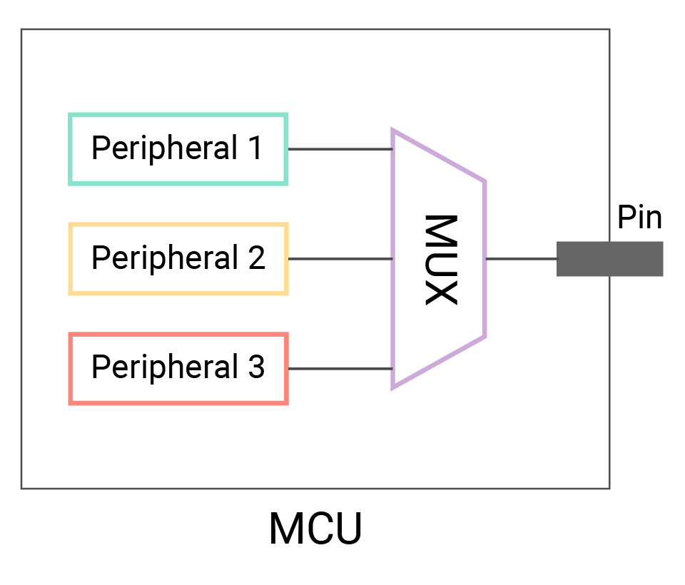
In fact, The chip provides a lot of functionality but contains a limited number of pins. Thus, physical pins on an MCU are often organized using a technique called pin multiplexing (MUX). With it, the state of a physical pin can be dynamically changed to serve different functions, such as a GPIO, an ADC input, and a UART transmit (TX) pin. BTW, UART uses two pins for communication and UART receive (RX) pin will be multiplexed to another pin.
Pin configuration on an MCU is typically done through software, as mentioned above, by writing to the peripheral registers that are associated with the pins that you want to use.
While pin multiplexing allows multiple peripherals to be routed to a single physical pin on an MCU, only one peripheral can be connected to a pin at a time.
What are pin names/ids for board?
Development boards have physical connectors called pins that allow you to easily connect external components and devices to an MCU. To identify and work with the MCU pins, the board will typically provide you with a set of pin names/ids or aliases. These pin names are usually more user-friendly and descriptive than the actual names of the MCU pins.
Silkscreens printed beside the pins typically indicate the functions of each pin, but they may not provide complete information about all capabilities of a particular pin.
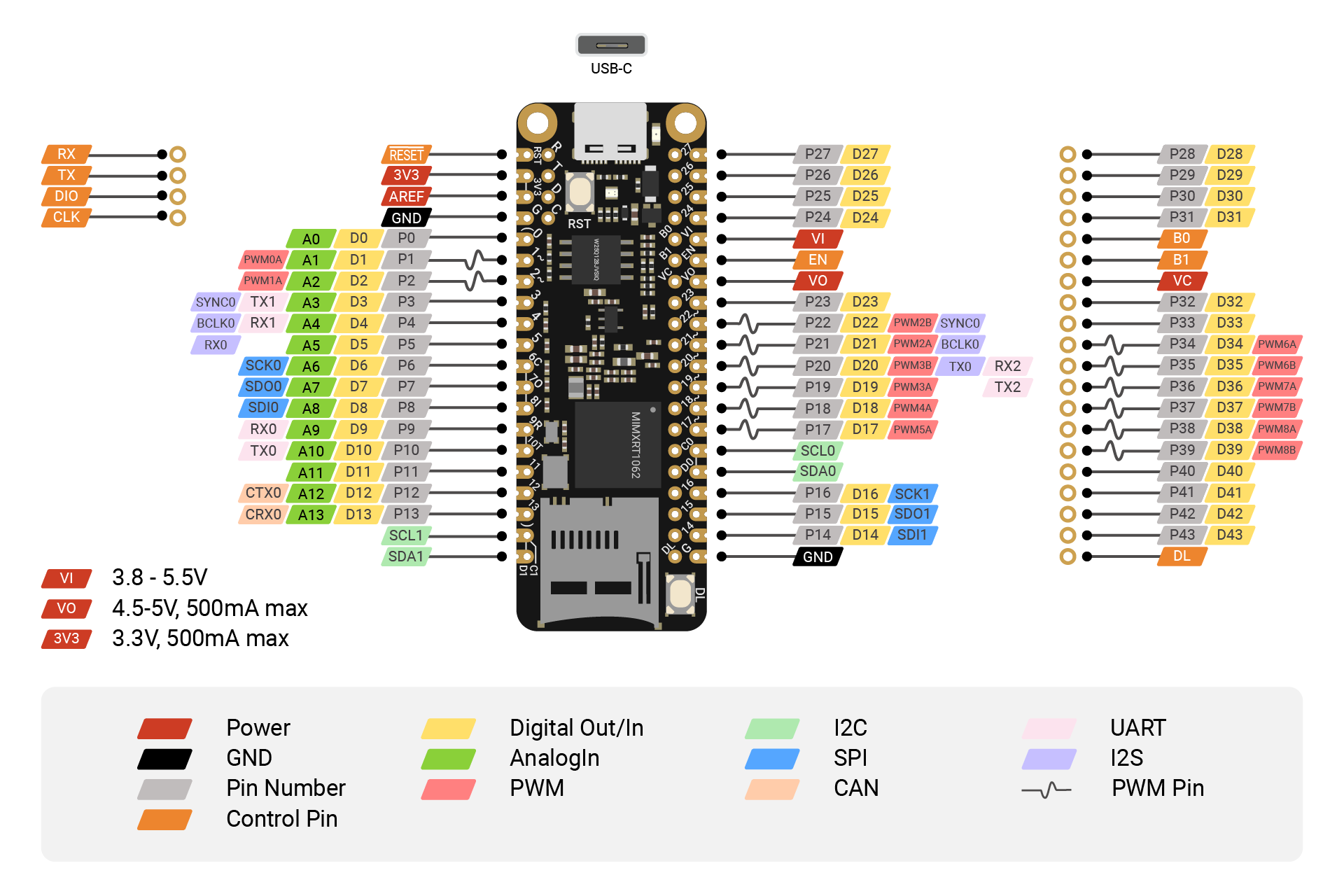
To help you understand the layout and functions of the pins in more detail, most development boards provide a pinout diagram. The pinout diagram provides a detailed illustration of the physical layout and connections of each pin on the board, as well as indicating the specific peripherals that are multiplexed onto each pin.
Here is the SwiftIO Micro pinout. You can notice most pins are multiplexed. For example, pin 9 (P9) can be used as GPIO, ADC, or UART receive pin.
When you work with a board based on its hardware abstraction, you can access the MCU pins using their user-friendly names and configure the corresponding peripheral using the provided APIs.
On some development boards, there may be several special pins that are not labeled on the board, but give you access to built-in hardware such as LEDs, buttons, or other components. These pins are usually reserved for specific functions and may be controlled by the board's firmware.