LED Blink
Now it's time for your first project! Let's start by learning how to use the most basic and commonly used component: the LED. It's everywhere in life, for lighting, indication, or decoration...
For those coming from the software programming world, you may be familiar with the traditional “hello world” program. In the world of electronics, we have a similar starter project: blinking an LED!
Learning goals
- Understand how the digital output signal works and learn GPIO peripheral.
- Learn about some basic components for electronic projects: diode, LED and resistor.
- Get to know ohm's law and figure out the relations between current, voltage, and resistance.
- Learn about circuit connections.
- Start to write code and learn some Swift programming knowledge.
- Blink LEDs using digital output.
- Learn how to use a timer to control LED.
🔸Circuit - LED
The circuits are all built when designing the board, so you don't need to connect any wires. And as mentioned before, the white sockets are used to build the circuit after the board is disassembled.
The image below shows how the LED module is connected to the SwiftIO Micro in a simplified way.
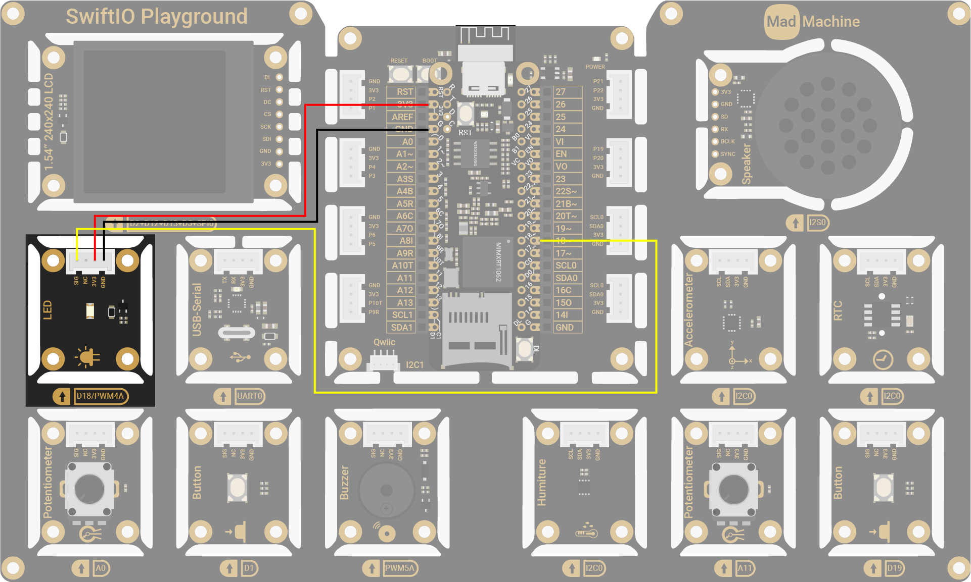
On circuit diagrams, the red line is usually for power and the black line for ground.
| LED Pin | SwiftIO Micro Pin |
|---|---|
| SIG | D18 |
| NC (Not Connected) | - |
| 3V3 | 3V3 |
| GND | GND |
The circuits above are simplified for your reference. Download the schematics here.
🔸Projects
1. LED blink
On your first try, let's make the LED blink.
Project overview
- The LED stays off by default.
- For the first second, the LED turns on due to high digital output.
- For the next second, the LED turns off due to low digital output.
- The LED turns on and off repeatedly...

Example code
You can download the project source code here.
// First import the SwiftIO and MadBoard libraries into the project to use related functionalities.
import SwiftIO
import MadBoard

// Initialize the specified pin used for digital output.
let led = DigitalOut(Id.D18)

// The code in the loop will run over and over again.
while true {
    //Output high voltage to turn on the LED.
    led.write(true)
    // Keep the LED on for 1 second.
    sleep(ms: 1000)

    // Turn off the LED and then keep that state for 1s.
    led.write(false)
    sleep(ms: 1000)
}
Code analysis
Here are some key statements for this program, make sure you understand them before you start to code.
// Comment
This is the comment for the code used to explain how the program works and also for future reference. It starts with two slashes.
import SwiftIO
import MadBoard
These two libraries are necessary for all your projects with the boards. In short, a library contains a predefined collection of code and provides some specified functionalities. You can use the given commands directly without caring about how everything is realized.
SwiftIO is used to control input and output of the board. It includes all the necessary functions to talk to your board easily. You'll dive deeper into it in the following tutorials.
MadBoard contains the ids of all types of boards. The ids for different types of boards may be different due to different board designs. Make sure the pin ids used in your code match the circuit.
let led = DigitalOut(Id.D18)
let is the keyword to declare a constant. A constant is like a container whose content will never change. But before using it, you need to declare it in advance. Its name can be whatever you like and it's better to be descriptive, instead of a random name like abc. If the name of your constant consists of several words, then except for the first word, the first letter of the rest words needs to be capitalized, like ledPin. This is known as the camel case.
The class, in brief, is more like a mold to create different examples, known as instances, with similar characteristics. The class DigitalOut provides ways to change the digital output on a specified pin, so all its instances share the functionalities. The process of creating an instance is called initialization.
The constant led is the instance of the DigitalOut class. To initialize it,
- specify the pin connected to the LED.
Idis an enumeration including the ids of all pins inMadBoard. As for enumeration, enum for short, it groups a set of related values. Just remember that the id needs to be written asId.D18. - the
modeof the digital pin ispushPullin most cases. - the
valuedecides the output state of the pin after it's initialized. By default, it outputs a low level, which means the LED is off by default.
Do you know how to initialize this LED to be on by default?
let led = DigitalOut(Id.D18, value: true)
In this way, pin D18 would work as a digital output pin and get prepared for the following instructions. Its voltage is low by default.
while true {
}
It's a dead loop in which the code will run over and over again unless you power off the board. The code block inside the brackets needs to be indented by 4 spaces.
Sometimes you find nothing that needs to run repeatedly, you can add sleep in it to make the board sleep and keep it in a known state.
led.write(true)
This statement makes the pin D18 output high voltage. The LED connected to that pin requires a high level to be on. Therefore, the LED turns on.
The led instance has access to all the instance methods in the DigitalOut. write() is one of its methods. You'll use dot syntax to access it: the instance name, followed by a dot, and the method at the end. Then you need the voltage level as its parameter, true for high voltage, false for low voltage. A value either true or false is of Boolean type.
sleep(ms: 1000)
The function sleep(ms:) has a parameter to define the time in milliseconds. During sleep time, the microcontroller would suspend its task.
An instance method needs dot syntax to invoke it, but a global function doesn't. You can directly call it.
Both methods and functions group a code block to realize specific functionality. Their difference is that a method belongs to a type, such as class, while a function is separately declared.
Delete the two sleep statements in the code and see what happens. Why?
The microcontroller executes state change of digital pins extremely quickly. If you change the output state between high and low without sleep, the LED will be on and off so quickly that you cannot notice it. So a short period is added here to slow it down. If you want the LED to blink faster, just reduce the sleep time.
When using methods/functions, why do some parameters need to add a name and others don't?
Let's look at the code below for example:
func write(_ value: Bool) { }
The parameter has an argument label and a parameter name. The argument label is used when calling a function. While there is an underscore “_” before the parameter name value, it means the label is omitted when invoking the function: led.write(true).
func sleep(ms: Int) { }
In this case, the parameter uses its parameter name as the argument label. So ms is necessary: sleep(ms: 1000).
- Try to blink the LED faster, such as 500ms on and 500ms off.
- Blink an LED with variable speed by manually changing the sleep time (i.e. a random number from 200 to 2000).
2. RGB LED
In this project, you'll control onboard RGB LED to emit different colors.
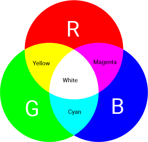
The onboard LED serves as an indicator during board connection and code downloading. It consists of red, green and blue LEDs in a package. You can control them separately by setting digital output signals.
The overall color of the light depends on the internal LEDs that are on. If only one of them is on, it shows its color. If two or three of the LEDs are on, the lights are mixed to create a different color, as in the image below. For example, if you turn on red and green, the combination of two lights results in yellow.
Project overview
- The onboard RGB LEDs are off by default.
- The red LED turns on for 1s.
- The green LED turns on for 1s.
- The blue LED turns on for 1s.
- The red and green LEDs are on for 1s, which results in a yellow color.
- The red and blue LEDs are on for 1s, which results in a magenta color.
- The green and blue LEDs are on for 1s, which results in a cyan color.
- The red, green, and blue LEDs are on for 1s, which results in a white color.
- All LEDs are off for 1s.
- Then repeat the process above.
Example code
You can download the project source code here.
import SwiftIO
import MadBoard

// Initialize the built-in red, green, blue LED.
// They need a low level to be turned on.
// So set the digital value of true to turn them off in the beginning.
let red = DigitalOut(Id.RED, value: true)
let green = DigitalOut(Id.GREEN, value: true)
let blue = DigitalOut(Id.BLUE, value: true)

while true {
    // Red.
    setRGB(true, false, false)
    // Green.
    setRGB(false, true, false)
    // Blue.
    setRGB(false, false, true)
    // Yellow (red + green).
    setRGB(true, true, false)
    // Magenta (red + blue).
    setRGB(true, false, true)
    // Cyan (green + blue).
    setRGB(false, true, true)
    // White (red + green + blue).
    setRGB(true, true, true)
    // Off.
    setRGB(false, false, false)
}

// Control red, green and blue LED with the given values.
// Apply low voltage to turn on the built-in LEDs.
// For example, if you want the red LED on, you should write false.
func setRGB(_ redOn: Bool, _ greenOn: Bool, _ blueOn: Bool) {
    red.write(!redOn)
    green.write(!greenOn)
    blue.write(!blueOn)
    sleep(ms: 1000)
}
Code analysis
let red = DigitalOut(Id.RED, value: true)
let green = DigitalOut(Id.GREEN, value: true)
let blue = DigitalOut(Id.BLUE, value: true)
RED, GREEN, BLUE (all capitalized) are used to control the onboard red, green and blue LEDs. These DigitalOut pins have been connected to the LEDs by default. You can change the output to turn these LEDs on/off.
The connection of these LEDs is different from the LED module. You need to apply a low level to turn them on. So the value is set to true to keep them off by default.
func setRGB(_ redOn: Bool, _ greenOn: Bool, _ blueOn: Bool) {
    red.write(!redOn)
    green.write(!greenOn)
    blue.write(!blueOn)
    sleep(ms: 1000)
}
This function aims to control three LEDs more conveniently. You just need to specify if they will be turned on.
The desired digital output is contrary to the actual LED state: output a low level to turn on the LED, high to turn it off. So use ! to toggle the boolean value.
In the while loop, turn on the RGB LED using different patterns to get different colors.
3. LED morse code
Blink the red LED at a different speed to generate the SOS signal.
Have you heard of Morse code? It encodes characters into a sequence of dashes and dots to send messages.
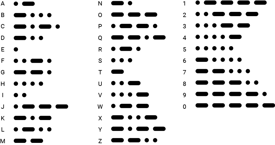
To reproduce it, you will use long flash and short flash respectively. So an SOS signal needs three short flashes, three long flashes, and then three short flashes again.
Project overview
- The LED is off by default.
- To represent the "S" signal, the LED blinks rapidly three times: on for 500ms and off for 500ms.
- Next, to represent the "O" signal, the LED blinks slower three times: on for 1s and off for 500ms.
- Finally, the LED blinks rapidly three times again to represent the "S" signal.
Example code
You can download the project source code here.
// Import the libraries to use all their functionalities.
import SwiftIO
import MadBoard

// Initialize the digital output pin.
let led = DigitalOut(Id.D18)

// Define the LED states to represent the letter s and o.
let sSignal = [false, false, false]
let oSignal = [true, true ,true]

// Set the LED blink rate according to the values in the array.
func send(_ values: [Bool], to light: DigitalOut) {
    // The duration of slow flash and quick flash.
    let long = 1000
    let short = 500

    // Iterate all the values in the array.
    // If the value is true, the LED will be on for 1s, which is a slow flash.
    // And if it’s false, the LED will be on for 0.5s, which is a quick flash.
    for value in values {
        light.high()
        if value {
            sleep(ms: long)
        } else {
            sleep(ms: short)
        }
        light.low()
        sleep(ms: short)
    }
}

// Blink the LED.
// At first, the LED starts 3 fast blink to represent s, then 3 slow blink to represent o, and 3 fast blink again.
// Wait 1s before repeating again.
while true {
    send(sSignal, to: led)
    send(oSignal, to: led)
    send(sSignal, to: led)
    sleep(ms: 1000)
}
Code analysis
let sSignal = [false, false, false]
let oSignal = [true, true, true]
An array stores a series of ordered values of the same type in a pair of square brackets. The values above are all boolean values.
Here, the two arrays store the info of two letters. Since there are only two states: fast or slow flash, a boolean value can represent two states: false corresponds to a quick flash, true for a slow flash.
The S signal needs three dots for morse code, so the three elements in the array are all false.
And O signal needs three dashes, so all elements are true.
func send(_ values: [Bool], to light: DigitalOut) {

}
This function controls the LED for a single letter. It needs two parameters: the first is an array of boolean values that stores the info for a letter; the second is the digital pin that the LED is connected to.
This function is to make your code more organized and clear. Of course, you can use other ways of abstraction.
Usually, it's better not to use the variable or constants that are declared out of the function itself. All stuff needed is passed in as its parameters. Thus the code becomes more reusable and clean. This practice would be really helpful as you work on great projects in the future.
let long = 1000
let short = 500
Set the duration of LED on-time. The values are stored in two constants to make the code more readable.
for value in values {

}
This is a for-in loop. It has two keywords: for and in. It's used to repeat similar operations and is usually used with arrays and ranges.
value represents the element in the array values. At first, it refers to the first element, then the second..., until it reaches the last one. It doesn't matter if you use value or a, b, c to name it. In this way, the code inside the curly brackets would repeat several times to iterate all elements in the array.
light.high()
Set high voltage. It works the same as led.write(true).
if condition {
    task1
} else {
    task2
}
This is a conditional statement. The if-else statement makes it possible to do different tasks according to the condition. The condition is always a boolean expression that will return either true or false. And it will usually use some comparison operators to evaluate the value as follows:
- Equal to:
a == b - Not equal to:
a != b - Greater than:
a > b - Less than:
a < b - Greater than or equal to:
a >= b - Less than or equal to:
a <= b
If the condition evaluates true, task1 will be executed and task2 will be skipped. If the condition is false, task2 will be executed instead of task1.
if value {
    sleep(ms: long)
} else {
    sleep(ms: short)
}
Back to the code above, the value is judged to know how long the LED should be on.
4. LED blink with timer
You will learn a new way to blink an LED - blink using a timer.
Project overview
- The blue LED blinks continuously: off for 500ms and on for 500ms.
- The red LED blinking slower: off for 1500ms and on for 1500ms.
What is a timer?
In your everyday life, you must be familiar with timers. For example, you are cooking meals, and the dish still needs another 30min. You can set a timer for 30min and do other work until the timer reminds you after 30min.
The timer here is quite similar. It is a software timer provided by Zephyr. You can set an expected time before executing a specified task. In this way, the microcontroller can do many other works before that. When the set time has elapsed, the microcontroller will stop the current work and go to execute the task. After finishing, it goes back to continue its previous work.

Class
Timer - this class is used to set interrupt at a specific time interval.
| Method | Explanation |
|---|---|
init(mode:period) | Initialize a timer. - mode: decide how many times the interrupt will happen: .oneShot or .period, .period by default to make the interrupt happen continuously. - period: the time interval, measured in ms. |
setInterrupt(start:_:) | Set the condition to trigger the interrupt. - start: decide whether it will start as you invoke this method, or you will start it manually later by using start(). - callback: set the task for interrupt. It needs functions with no parameter and return value. |
Example code
You can download the project source code here.
// Import the SwiftIO library to control input and output and the MadBoard to use the id of the pins.
import SwiftIO
import MadBoard

// Initialize a digital pin for LED module.
let redLed = DigitalOut(Id.D18)

// Initialize the onboard blue LED.
let blueLed = DigitalOut(Id.BLUE)

// Initialize a timer for 1500ms.
let timer = Timer(period: 1500)

// Define a new function used to toggle the LED.
func ToggleLEDSwitch() {
    redLed.toggle()
}

// Set an interrupt to reverse the LED state every time the interrupt occurs.
timer.setInterrupt(ToggleLEDSwitch)

// Blink onboard blue LED.
while true {
    blueLed.high()
    sleep(ms: 500)

    blueLed.low()
    sleep(ms: 500)
}
Code analysis
let timer = Timer(period: 1500)
Initialize a timer by setting the time interval.
- The timer's
modeisperiodby default, which means the interrupt occurs every time the specified interval elapsed, that is, the specified task will be executed periodically. If it is set tooneShot, the timer interrupt happens once, so the task will be done once. - The parameter
periodsets the time interval in milliseconds.
timer.setInterrupt(ToggleLEDSwitch)
Set the task to be executed if the time interval has elapsed. It needs a function as its parameter, ToggleLEDSwitch as above. So every 1500ms the state of redLed changes to make it blink.
while true {
    blueLed.high()
    sleep(ms: 500)

    blueLed.low()
    sleep(ms: 500)
}
In the loop, the microcontroller will do other work. Here you will make the onboard blue LED blink every 500ms.
🔸API
DigitalOut
As indicated by its name, this class is used to control digital output, to get high or low voltage.
| Method | Explanation |
|---|---|
init(_:mode:value:) | Initialize a digital output pin. Parameter: - idName: the pin id which is listed in the Id enumeration. - mode: the output mode of the pin, pushPull by default. - value: the output value after initialization, false by default. |
write(_:) | Set the pin to output high or low voltage. Parameter: - value: a boolean type: true corresponds to a high level and false corresponds to a low level. |
toggle() | Reverse the digital output. |
high() | Output high voltage. |
low() | Output low voltage. |
sleep(ms:)
Make the microcontroller suspend its work for a certain time, measured in milliseconds.
🔸Background
What is digital signal?
In electronics and telecommunication, electronic signals carry data from one device to another to send and receive all kinds of information. These signals are time-varying, meaning that the voltage or current changes over time in a specific pattern that carries information. Digital and analog signals are two different types of electronic signals used to transmit and process information.
In this tutorial, you'll focus on digital signals. Digital signals typically take on two distinct voltage levels, which can represent binary 1 or 0 values. These values can be combined in various ways to represent more complex information, such as text, images, or sound.

Here are different expressions to represent two states:
| Logic 1 | Logic 0 |
|---|---|
| true | false |
| high | low |
| 3.3V | 0V |
For our board, 3.3V represent true and 0V represent false. Of course, there are many other possibilities, like 5V for true...
Digital signals are ideal for working with components that have discrete states, such as LEDs (on/off) and buttons (pressed/released).
Peripheral - GPIO
The peripheral GPIO (general-purpose input/output) allows sending and receiving digital signals between MCUs and various devices.
GPIO pins can be configured as either input or output pins using software.
- When a GPIO pin is configured as an output, it can be set to either a high or low voltage level to control the state of an external device, such as turning an LED on or off.
- When a GPIO pin is configured as an input, it can read the voltage level of an external signal, either high or low.
In this tutorial, you'll make a GPIO pin output digital signal to control the LED. For the LED module on your kit, when you apply a high signal, it will turn on, and if you apply a low signal, it will be off.
🔸New component
Diode
The diode is a polarized component. It has a positive side (anode) and a negative side (cathode). After being connected in the circuit, the current can only flow in a single direction, from anode to cathode. If you connect it in an opposite direction, the current will not be allowed to pass through.

LED
LED (Light-emitting diode) is a type of diode that convert electrical energy into light. Only when you connect it in the right direction - connect the anode to power and the cathode to ground - is the current allowed to flow, lighting up the LED.
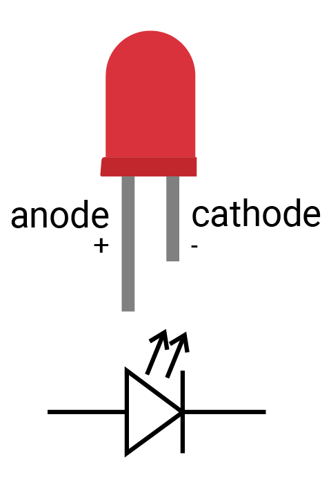
How to identify the two legs of an LED?
- Typically the long leg is positive and the short leg is negative.
- Alternatively, sometimes you will find a notch on the negative side.
The LED allows a limited range of current, usually no more than 20mA. So you should add a resistor when connecting it to your circuit. Or the LED might burn out when driving too much current.
LED Circuit connection
When you connect the LED in the circuit, there are two cases to control the LED:
- Connect the anode to a digital output pin and cathode to ground. When connected this way, the LED turns on when the pin outputs a high signal.
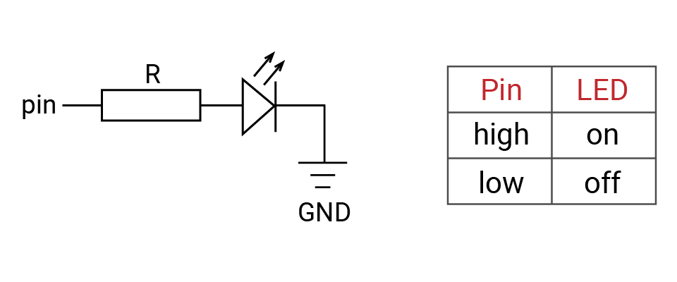
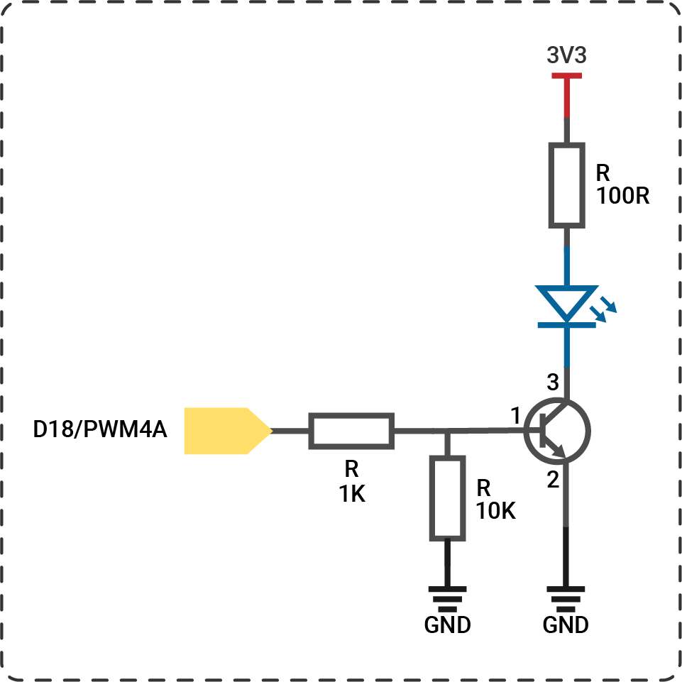
Pin is a digital output pin, R is a resistor, ![]() is an LED, and GND is ground
is an LED, and GND is ground
- Another method is to connect the anode to a power source and connect the cathode to a digital output pin. When the digital output signal is high, there is no voltage difference between two ends of the LED, but when the digital signal is low, current is allowed to flow, causing the LED to turn on. This is how the built-in LED works on the SwiftIO Micro.
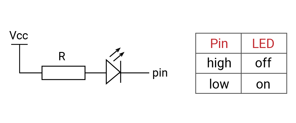
Vcc is a power source, R is a resistor, ![]() is an LED, and pin is a digital output pin
is an LED, and pin is a digital output pin
There are many types of LEDs with different colors and sizes. The LED on your kit is a small variant designed to be convenient for mass production. You could see this article for more details on LED.
Resistor
Resistor functions as a current-limiting component that, just as its name suggests, can resist the current in the circuit. It has two legs. You can connect it in either direction as it is not polarized. Its ability to resist the current, called resistance, is measured in ohm (Ω).

Symbol:  (International),
  (US)
(US)
How can you tell how much resistance a resistor provides?
Each resistor has a specific resistance. Note the colored bands in the diagram. Each band corresponds to a certain number. Here is an online guide and calculator to determine how to total the value of all the bands together.
What's the resistance of the sample resistor R1 pictured above, as well as the resistors R2 and R3 below? See below for the answer!


Answer
- R1: 10KΩ with a tolerance of ± 5%
- R2: 330Ω with a tolerance of ± 5%
- R3: 470KΩ with a tolerance of ± 1%
This kind of resistor is useful primarily when you DIY some stuff. The kit use surface mount resistors as they are smaller and more suitable for mass production.
🔸New concept
Ohm's law
When starting with electronics, you must get familiar with these three concepts: voltage, current, and resistance:
- Voltage measures potential energy between two points.
- Current describes the rate of flow of electric charges that flow through the circuit.
- And resistance is the capability to resist the flow of current.
An intuitive and common analogy is water pressure in a tank. Imagine a water tank with water inside and an opening at the bottom.
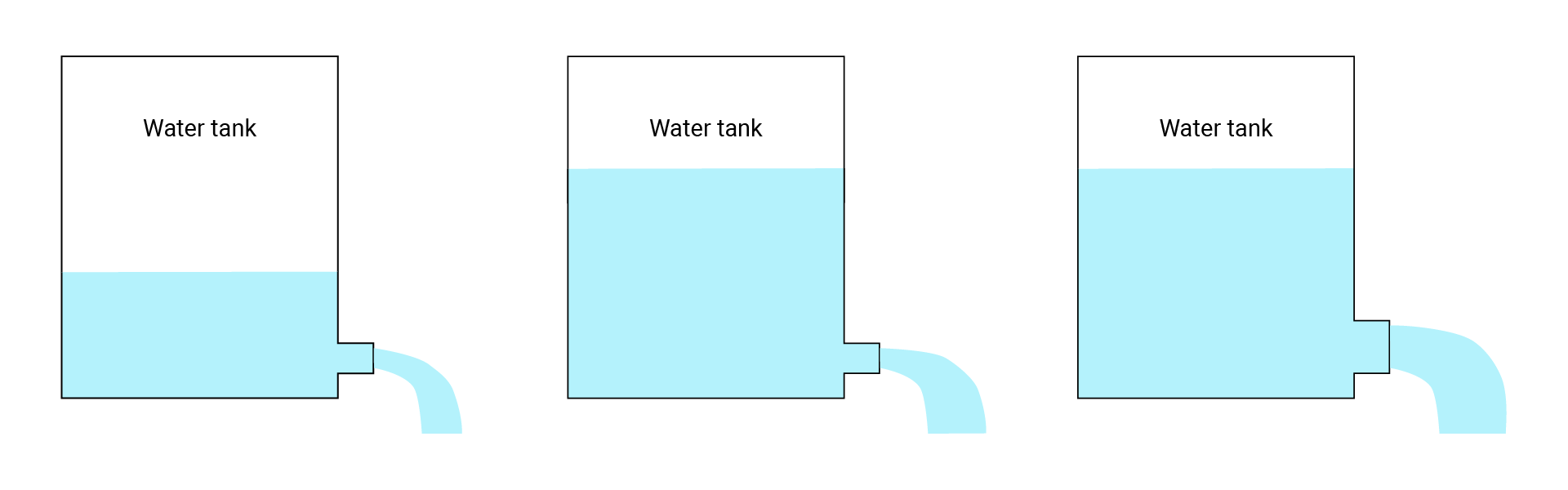
In this scenario, the water pressure (water level) is like the voltage, the opening is like resistance, and the amount of water spilling out is like the current.
- Looking at the first figure, very little water will come out (current) because there isn't much pressure (voltage) and the opening is small (resistance).
- In the second example, we've increased the water level (voltage), but kept the same sized opening (resistance), which results in an increase in the flow of the water (current).
- Finally, in the last one, we've also increased the size of the opening (reduced resistance), keeping the water level (voltage) the same, resulting in another increase in flow (current).
Ohm's law describes how voltage, current and resistance interact with each other and work similarly to the water tank above. The formula is:
V = I * R
- V: voltage (unit: volts or V)
- I: current (unit: amps or A)
- R: resistance (unit: ohm or Ω)
Using some simple algebra, we can also put forward the following formulas:
R = V / I
and
I = V / R
As stated previously, all digital pins on the SwiftIO Micro output a high signal of 3.3V. For example, if the resistance in the circuit is 330Ω, the current would be 3.3 / 330 = 0.01A.
Given an LED with the following characteristics, how many ohm resistors should you use to complete the circuit, using the 3.3V DigitalOut pin source?
- Forward current: 15mA max
- Forward voltage: 3.0V
Here is the equation:
R = (Vcc - VF) / IF
- Vcc: supply voltage
- VF: forward voltage for the LED, that is, voltage drop as the current across the LED.
- IF: forward current for the LED (usually 10-20mA). It's the maximum current. If you don't have the specs about LED, you could normally suppose it to be 20mA.
Btw, the resistance of the LED itself is little so you could ignore it.
Answer
The resistor needed for the LED is: R = (3.3 - 3.0) / 0.015 = 20Ω
Frequently you will be unable to find a resistor that matches the exact theoretical value. When this happens, you can use a resistor that has slightly greater resistance.
In general, the resistance calculated is a minimum requirement. You can also choose a resistor with larger resistance. Doing so will cause the LED's brightness to change with it. Greater resistance will cause the LED to be dimmer.
You can also try this online Ohm's law simulator to get more familiar with it.
Series circuit and parallel circuit
Series and parallel circuits are the ways to connect more than two devices in the circuit.
- In a series circuit, devices are connected end-to-end in a chain, like R1 and R2. The current flows through them in one direction from positive to negative. And the current flowing through each device is the same: IR1 = IR2.
- In a parallel circuit, devices share two common nodes, like R3 and R4. Node a connects both two devices, so the current flows through both of them. The voltages between the two devices are the same: VR3 = VR4.
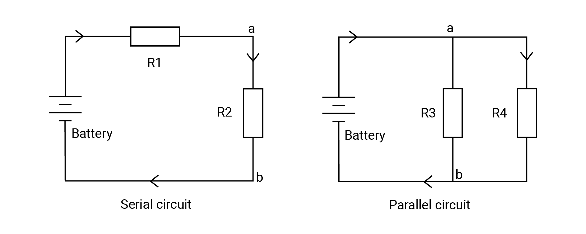
Calculate the current and voltage of each resistor in the circuit above using Ohm's law.
Suppose R1 is 100Ω and R2 is 200Ω, the voltage supply is 3V.
- RTotal = RR1 + RR2 = 300Ω
- IR1 = IR2 = 3V / 300Ω = 0.01A
- VR1 = 0.01A x 100Ω = 1V
- VR2 = 0.01A x 200Ω = 2V
Suppose R3 is 100Ω and R4 is 200Ω, the voltage supply is 3V.
- VR3 = VR4 = 3V
- IR3 = 3V / 100Ω = 0.03A
- IR4 = 3V / 200Ω = 0.015A
- I = IR3 + IR4 = 0.045A
You could also get total resistance in the circuit:
- V / RTotal = VR3 / RR3 + VR4 / RR4
- 1 / RTotal = 1 / RR3 + 1 / RR4
- Thus you get the formula for the total resistance in the circuit: RTotal = (RR3 x RR4) / (RR3 + RR4) ≈ 66.67Ω
In your real situation, the circuit would not be that easy. The series and parallel circuits would both be used when building the circuit.
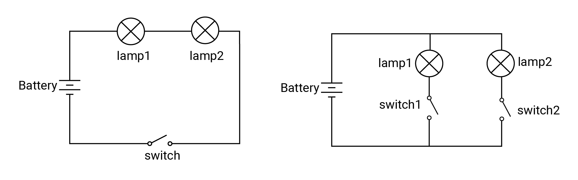
Let's look at an example.
- In the first circuit, the two lamps are connected in series, so the switch can control both of them. If any of the lamps breaks down, even if the switch is closed, the other lamp will not be lit.
- In the second circuit, the two lamps are connected in parallel, you can control any of them by using the switch connected in series: switch1 controls the lamp1, switch2 controls the lamp2. The two lamps work separately.
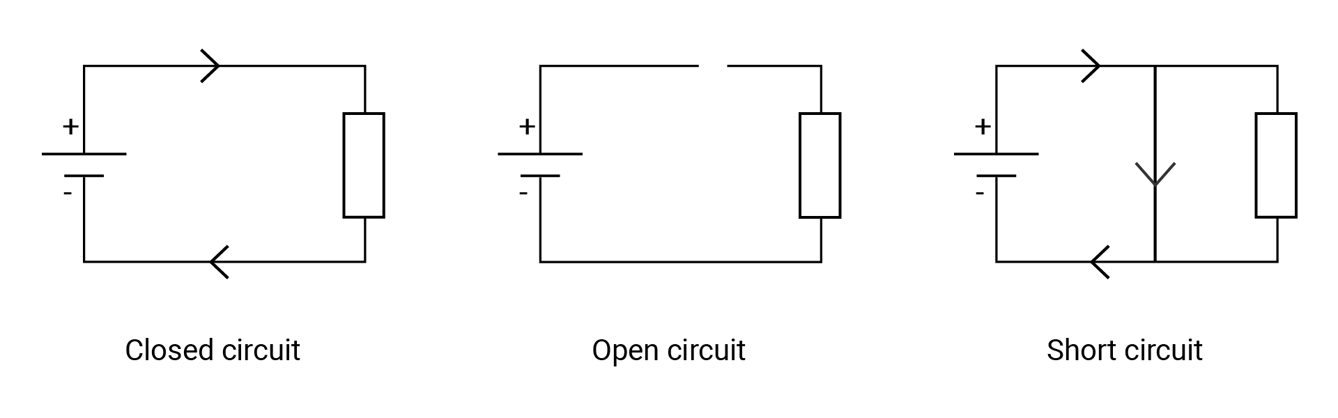
Open, closed and short circuit
In addition to the previously mentioned types of circuits, there are three more concepts you need to know about: open circuit, closed circuit, and short circuit.
- The first figure is a closed circuit. This allows current to flow freely from the positive terminal through a load that consumes electric power, finally returning to the negative terminal.
- In an open circuit, there is a gap somewhere on the circuit, therefore disallowing any current to flow through it.
- Current tends to flow through the path with lower resistance, if you accidentally connect the positive to the negative terminal of the power supply, the current will flow directly through this path and bypass the other paths with higher resistance. The resistance of wires is so small that you could normally ignore it. This causes a short circuit. It can be dangerous as it can cause overheating, damage to components, or even fires.
In a complete circuit, the current will always flow from the point of higher voltage (usually power) to the one of lower voltage (usually ground or GND). Consumed energy is turned into light, heat, sound and many other forms.
If you were to connect the power directly to the ground using a wire, this would cause a short circuit. It can (and usually do) cause damage to your circuit and board, and is also very possible to start a fire.
Another warning: if you're not careful about selecting an appropriately strong resistor to resist the level of current flowing through the circuit, the devices can be burnt and damaged (and additionally cause a fire hazard).
🔸Go further
Push-pull and open-drain
There are typically two pin configurations: push-pull and open-drain.
Push-pull
A push-pull output can both source and sink current. This is how it got its name since it pushes the signal high and pulls it low.
In a push-pull circuit, two active devices are used to drive a load. One device is used to "push" current into the load, while the other device is used to "pull" current out of the load. The two devices switch back and forth, following the internal signal, to create the output.
It can drive a signal over a longer distance and have less susceptibility to noise compared to open-drain outputs.
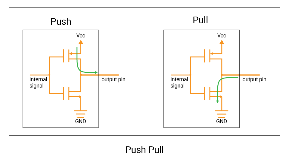
The GPIO pins are configured to push-pull by default. So you can set them to output high or low voltage.
Open-drain
In contrast, an open-drain output can only sink current.
An active device is used to pull the output voltage to a low state, but does not actively drive it to a high state. It acts like a switch that connects the signal line to the ground, pulling the voltage level of the signal line low. This is called "drain" because it is "draining" current away from the signal line. And if it is turned off, the signal line is in an "open" state, not connected to either power or ground. This means that there is no current flowing through the line and it would float.
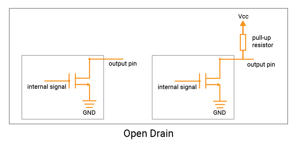
To drive the signal high, an external pull-up resistor can be used to connect it to the high voltage level (Vcc), which will pull the output high when no other device is actively driving the signal. This means that the current flowing through the pull-up resistor is sourced by the voltage source, not by the open-drain output.
The use of open-drain outputs is useful in situations where multiple devices need to share a single communication line, such as the I2C bus.